Confidential and Proprietary Information of ZTE CORPORATION 65
Chapter 4
Networking Mode and
System Configuration
This chapter covers the following topics:
Configuration Description
System Networking and Standard Configuration
System Application Mode
Configuration Description
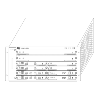
The whole system, with a height of 5U, consists of six layers,
and uses the opposite insertion structure. The front and back of
the system are shown in
Figure 19, and Figure 20.
In the
Figure 19, the top two layers are the TAA board slots H1
and H2, and the two TAA boards can either be configured in the
active/standby mode or the dual-system mode. Under the TAA
boards are the line boards, including eight slots, and they are
separated into two groups (Group A and Group B). The Group A
consists of A1, A2, A3 and A4, and the Group B consists of B1,
B2, B3 and B4.
The board types that can be installed interchangeably in the
slots are shown in
Figure 21. The 100 M Ethernet transparent
transmission board can be inserted in all the six slots except A1
and B1, and the 155 M electrical interface board can be inserted
in the six slots except A1 and B1.
The
Figure 20 is the rear view of the system, including six slots.
The top G1 and G2 slots are the special slots of the PCI and
NOWC, and the two slots are in the same height as the H1 and
H2 slots. The lower four slots are the slots of the leading-out
boards, including B1L, B2L, B3L and B4L, and they are the slots
of the leading-out boards of the Slots B1, B2, B3 and B4. They
can be inserted either with 2 M leading-out boards or Ethernet
leading-out boards, depending on the line boards inserted in
Front Slots B1, B2, B3 and B4.
 Loading...