Chapter 3 Hardware Overview
MGS3520 Series User’s Guide
27
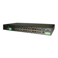
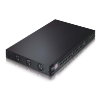
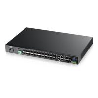
Figure 10 MGS3520-50 Rear Panel: AC/DC Model
The following table describes the port labels on the front panel.
3.1.1 Console Port
For local management, you can use a computer with terminal emulation software configured to the
following parameters:
• VT100
• Terminal emulation
• 9600 bps
• No parity, 8 data bits, 1 stop bit
• No flow control
Connect the male 9-pin end of the console cable to the console port of the Switch. Connect the
female end to a serial port (COM1, COM2 or other COM port) of your computer.
Console Port
DC Power Connection
Signal slot
AC Power Connection
Table 2 Front Panel Connections
LABEL DESCRIPTION
Power Switch This is for DC model only. After you connect the DC power properly (see Section 3.1.4.2 on
page 30.), put the power switch in the ON position to turn on the Switch.
Power
Connection
Connect an appropriate power supply to this port.
RJ-45 Ethernet
Ports
Connect these ports to a computer, a hub, an Ethernet switch or router.
SFP Slots Use transceivers in these slots for fiber-optic or copper connections to a computer, a hub, a
switch or router.
Four or Two
Dual Personality
Interfaces
Each interface has one 1000BASE-T RJ-45 port and one transceiver slot, with one port or
transceiver active at a time.
• Four 10/100/1000 Mbps RJ-45 Ports:
Connect these ports to high-bandwidth backbone network Ethernet switches using
1000BASE-T compatible Category 5/5e/6 copper cables.
• Four Transceiver Slots:
Use mini-GBIC or SFP transceivers in these slots for connections to backbone Ethernet
switches.
Console Port The console port is for local configuration of the Switch.
Signal slot Connect the signal input pins to signal output terminals on other pieces of equipment.
Connect the signal output pins to a signal input terminal on another piece of equipment.
 Loading...