Installation manual 2N® IP Force
•
•
•
•
•
•
•
•
•
•
•
•
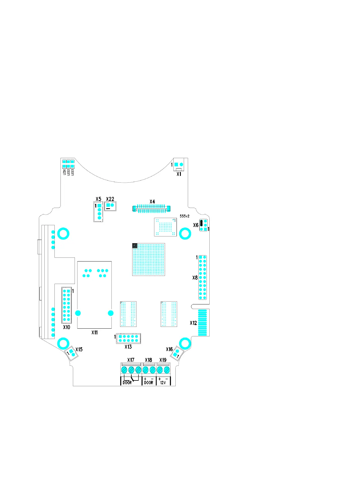
X8–Extending module (RFID card reader or additional switch)
X10–Buttons 1 through 4
X11–LAN
X12–Servicing connector
X13–Keypad module
X15– Left-hand microphone
X16–Right-hand microphone
X17–Relay NO and NC contactmax. 30 V / 1 A AC/DC. Used for connection of non-critical devices only
(lights, e.g.).
X18– Switched output9 up to 13 V DCdepending on power supply (PoE: 9 V; adaptor: power supply voltage
minus 1V), max 700mA
X19– Power input12 V ±15 % / 2 A DC
LED1/2–System status indicators
LED3–LAN connection activity indicator
2N
®
IP Force Connectors, PCB Version 555v2