Installation manual 2N® IP Uni
Dimension for wall (surface) mounting
2.3 Electric Installation
This subsection describes how to connect2N
®
IP Uniinto your Local Area Network (LAN) and
how to connect supply voltage and the electric lock.
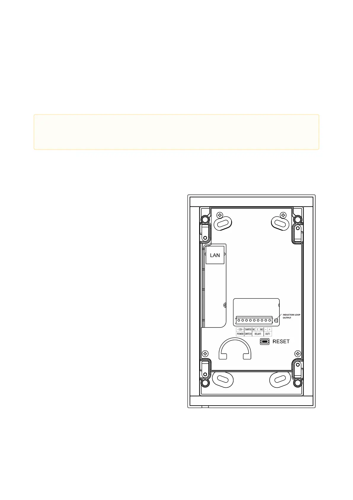
PCB Connectors
Description of Connectors
LAN– LAN connector
OUT1– Active switched output
RELAY1– Relay NO/NC contacts. Used
for connection of non-critical devices
only (lights, e.g.).
TAMPER– Tamper switch
POWER– Power input
RESET– RESET button
INDUCTION LOOP OUTPUT – Output for
2N
®
Induction Loop. Connector type JST
SHR-02V-S.
•
Caution
The device must be part of the electrical system of the building.