EasyManuals Logo

3Com Switch 4210 Series User Manual

3Com Switch 4210 Series
80 pages
To Next Page IconTo Next Page
To Previous Page IconTo Previous Page
Page #27 background imageLoading...
Page #27 background image
Connecting Console Cable 27
Figure 25 Ground through an AC PE wire
Connecting Console
Cable
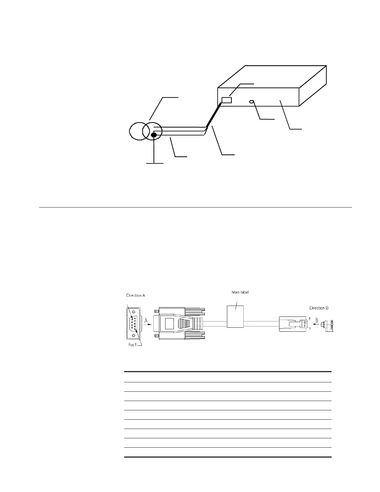
Console Cable A Console cable is an 8-core cable. One end of the cable is a crimped RJ-45
connector for the connection to the Console port of the switch, and the other end
is a DB-9 female connector for the connection to the serial port on the Console
terminal, as shown in Figure 26.
Figure 26 Console cable
(1) AC power input (2) Grounding screw (3) Power transformer
(4) PE ground wire (5) Three-wire AC power input cable (6) Ethernet Switch
(2)
(1)
(2)
(3)
(4)
(5)
(6)
Table 13 Console cable pinouts
RJ-45 Signal Direction DB9 (modem) DB9 (console)
1 RTS 7 8
2 DTR 4 6
3 TXD 3 2
4 CD 1 5
5 GND 5 5
6 RXD 2 3
7 DSR 6 4
8 CTS 8 7

Table of Contents

Questions and Answers:

Question and Answer IconNeed help?

Do you have a question about the 3Com Switch 4210 Series and is the answer not in the manual?

3Com Switch 4210 Series Specifications

General IconGeneral
Model3Com Switch 4210 Series
LayerLayer 2
ManagementCLI
VLAN SupportYes
QoSYes
Jumbo Frame SupportYes
Power SupplyInternal
Operating Temperature0°C to 40°C
Relative Humidity10% to 90% non-condensing
Uplink Ports4 SFP ports (on 24-port model), 4 SFP ports (on 48-port model)
Dimensions (W x D x H)440 x 260 x 44 mm (24-port model), 440 x 260 x 44 mm (48-port model)

Related product manuals