6
1.0 PRODUCT APPLICATION
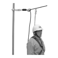
1.1 PURPOSE: 3M Engineered Systems provide permanent anchorage for Personal Fall Arrest Systems (PFAS) and Personal
Fall Restraint Systems (PFRS). They typically employ a fl exible or rigid anchor line with mobile anchorage connection
points to ensure user connection along the entire length of the system.
1.2 SUPERVISION: Installation of the Engineered System
1
must be supervised by a Certifi ed Installer
2
.
1.3 INSTALLATION DOCUMENTATION: The Engineered System is designed by a 3M Certifi ed Installer to meet the specifi c
requirements of the product application and location. On completion of the installation, the Certifi ed Installer will provide
an Installation Packet including the following:
System Documentation System Certifi cate System Label
The Certifi ed Installer will provide as a
minimum:
• Design information including: End
Loads, Intermediate Loads, Cable
Defl ection, Fabrication Detail,
Maximum Number of Users, and
specifi cs regarding User Equipment
and Test Requirements.
• User Instruction Manual
• Product Warranty
• Installation Serial Number
• Rescue Plan explaining how to rescue
someone in the event of a fall (Fall
Arrest installations only). This is
an additional service for which the
Installer may require an additional
charge.
The System Certifi cate is signed by a
representative of the Installation Company
and will include the following detail:
• Location of the Installation
• Unique Identifi cation Number
• Number and Length of Systems
• Maximum number of Users per Span
and per System
• Type and Maximum Length of Lanyards
specifi ed
• Installation Date
• Date of Next Required Service
• Name and Contact Detail for the
Installation Company
• Name of the Installation Engineer and/
or Supervisor
The System Label is located at the entrance
point to the system and will include the
following detail:
• Maximum Number of Users per Span
and per System
• Type and Maximum Length of Lanyards
specifi ed
• Installation Date and details regarding
the Installation Company
• Next Service Date
• System Serial Number
• Minimum Ground Clearance
• Contact Detail for the Installation
Company
1.4 TRAINING: This equipment must be installed and used by persons trained in its correct application. It is the
responsibility of the users and installers of this equipment to ensure they are familiar with these instructions, trained in
the correct care and use of this equipment, and are aware of the operating characteristics, application limitations, and
consequences of improper use of this equipment.
1.5 LIMITATIONS: Always consider the following limitations when designing and installing the Engineered System:
• Anchorage: Structure on which the Engineered System is mounted must meet the Anchorage specifi cations defi ned
in Table 1 and the 3M™ DBI-SALA
®
Installed Systems Calculation Software.
• Fall Path and SRL Locking Speed: A clear path is required to assure positive locking of an SRL. Situations which do
not allow for an unobstructed fall path should be avoided. Working in confined or cramped spaces may not allow the
body to reach sufficient speed to cause the SRL to lock if a fall occurs. Working on slowly shifting material, such as
sand or grain, may not allow enough speed buildup to cause the SRL to lock.
• Hazards: Use of this equipment in areas with environmental hazards may require additional precautions to prevent
injury to the user or damage to the equipment. Hazards may include, but are not limited to: heat, chemicals,
corrosive environments, high voltage power lines, explosive or toxic gases, excessive vibration, moving machinery,
sharp edges, or overhead materials that may fall and contact the user or Personal Fall Arrest System.
• Fall Clearance: There must be suffi cient clearance below the user to arrest a fall before the user strikes the ground
or other obstruction. Fall Clearance is infl uenced by the following factors:
• Deceleration Distance • Worker Height • Elevation of Anchorage Connector
• Free Fall Distance • Movement of Harness Attachment Element • Connecting Subsystem Length
Check the Certifi ed Installer’s Post-Installation Documentation for specifi cs regarding system design and fall clearance
calculation. Changes in system location, equipment placement, etc. require review and revision of original clearance
calculations. Contact the Certifi ed Installer or 3M Fall Protection for assistance.
• Swing Falls: Swing Falls occur when the anchorage point is not directly above the point where the fall occurs (see
Figure 3). The force of striking an object while swinging from the pendulum eff ects of a Swing Fall can cause serious
injury (Figure 3-1). Swing Falls can be minimized by limiting the horizontal distance between the user and the
anchorage point (H). In a Swing Fall, the total vertical fall distance will be greater than if the user had fallen directly
below the anchorage point, thus increasing Fall Clearance required to safely arrest the user’s fall (Figure 3-2). See
the PFAS manufacturer’s instructions for details regarding Swing Falls and Fall Clearance calculation.
• Sharp Edges: The Engineered System must be installed so defl ection of the anchor line in a fall arrest does not bring
the anchor line into contact with a sharp edge or any other article that may damage the anchor line. Avoid working
where Lifeline or Lanyard components of the attached Personal Fall Arrest System (PFAS) can contact or abrade
against unprotected sharp edges (see Figure 4). Where contact with a sharp edge is unavoidable, cover the edge with
protective material (A).
1 Engineered System: An application specifi c fall protection system designed, analyzed, evaluated, specifi ed, and installed by a 3M Certifi ed Installer.
2 Certifi ed Installer: A person certifi ed by 3M with extensive knowledge, training, and experience in the fall protection and rescue fi eld who is capable of designing,
analyzing, evaluating, and specifying fall protection and rescue systems to the extent required by applicable regional and national standards.
 Loading...
