2
Installation Instructions G5 - Revision C, October 2019
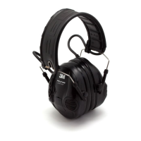
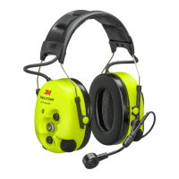
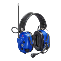
3M™ Drive-Thru System Model G5
4. Troubleshooting. . . . . . . . . . . . . . . . . . . . . . . . . . . . . . . . . . . . . . . . . . . . . . . . . . . . . . . . . . . 47
A. Headset Indicator Lights .....................................................................................................47
B. General Troubleshooting ....................................................................................................48
C. Battery and Battery Charger Troubleshooting................................................................51
5. Appendix: Declaration of Conformity. . . . . . . . . . . . . . . . . . . . . . . . . . . . . . . . . . . . . 53
6. Appendix: Basestation Specifications . . . . . . . . . . . . . . . . . . . . . . . . . . . . . . . . . . . . 58
A.
Physical ..................................................................................................................................58
B. Electrical ................................................................................................................................58
C. Functional ..............................................................................................................................58
D. Antennas ................................................................................................................................58
E. Magnetic Loop Detectors...................................................................................................58
7. Appendix: Induction Loop and Vehicle Detector Board Specifications . . 59
A. Internal Vehicle Detector Board Specifications ..............................................................59
B. Saw - In Loop Specifications..............................................................................................59
C. Prefab Loop Specifications.................................................................................................59
8. Appendix: G5 Charger Specifications . . . . . . . . . . . . . . . . . . . . . . . . . . . . . . . . . . . . 60
A. Physical ..................................................................................................................................60
B. Electrical ................................................................................................................................60
C. Functional ..............................................................................................................................60
9. Appendix: Best Practices. . . . . . . . . . . . . . . . . . . . . . . . . . . . . . . . . . . . . . . . . . . . . . . . . . .61
A. PreAmp Setting.....................................................................................................................61
B. Volume Control.....................................................................................................................61
C. Optimizing Installation.........................................................................................................61
D. Dealing with Delay/Echo ....................................................................................................62
10. Appendix: 3M™ Acoustic Kit Installation Guide . . . . . . . . . . . . . . . . . . . . . . . . . .63
A.
System Components............................................................................................................63
B. Installation Guidelines - Separate Housings ....................................................................63
C. Installation Guidelines - Single Housing...........................................................................64
11. Appendix: Loop and Cable Condition Test . . . . . . . . . . . . . . . . . . . . . . . . . . . . . . . .66
A. Lineal Conductor Resistance and Inductance.................................................................66
B. Insulation Resistance ...........................................................................................................66
12. Appendix: Upgrading a Single-Lane Basestation to a Dual-Lane . . . . . . . . .67
13. Index . . . . . . . . . . . . . . . . . . . . . . . . . . . . . . . . . . . . . . . . . . . . . . . . . . . . . . . . . . . . . . . . . . . . . . .72

 Loading...