3M™ PROTÉGÉ PLUS
PORTABLE MULTI-GAS MONITOR
MAINTENANCE
8006569, Rev. C/June 2018
7-4
7.1.2. SPAN CALIBRATION
1. Refer to Section 7.1.1.1. Connecting the Gas Cylinder to Monitor to connect the gas cylinder.
2. With the device powered on, and if it is not powered on, press and hold the Right Button until the
release IN 3 SECONDS screen appears, then Zero Calibration display.
3. Press the right button to scroll down the menu and select SPAN, then press the left button to
confirm the selection.
4. If the Span Calibration is confirmed, a screen stating SEN 1 appears. Select SEN 1 or press the
right button to scroll down the Sensor Types.
WARNING: READ, UNDERSTAND AND FOLLOW THE INSTRUCTIONS, INCLUDING
LABELS AND MSDS PROVIDED BY THE MANUFACTURER OF THE
CALIBRATION GAS. FAILURE TO DO SO COULD RESULT IN INJURY OR
DEATH.
NOTE: See “Sensor K-Factors” on page 64 to calibrate an instrument to read combustible
gases other than methane.
NOTE: The device has an automatic second timer that is enabled when countdown screen
is displayed (refer to Figure 7-4: SPAN Calibration). If you are unable to apply gas
to the sensors within the specific time, the monitor will return to the normal reading
mode.
NOTE: The device can be span calibrated using either individual calibration gas cylinders
that contain one specific target gas or a gas mixture cylinder that contains a mixture
of each of the target gases. If using individual gas cylinders to span calibrate, the
span calibration procedure must be completed for each sensor.
NOTE: The device automatically looks at the sensors installed and adjust the Apply Gas
timer accordingly. Sometimes when All is selected, a few sensors (IR sensors) may
return a fail during the span calibration due to the difference in time requirements.
When this occurs, we recommend selecting the individual sensor.
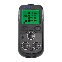
NOTE: SEN 1, 2, 3, 4 represents the sensor types that are shown on the LCD (refer to
Figure 7-3:). SEN 4 represents Bump All Sensors. If selecting EXIT, the device turns
back to the BUMP screen.