3M
™
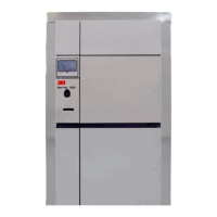
Steri-Vac
™
Sterilizer/Aerator GS Series
Site Planning and Installation Guide
70-2011-5643-0 Issue Date: 10/2015
Installation Verification Form: 3M
™
Steri-Vac
™
Sterilizer/Aerator GS Series
Facility Name:
Address:
City: State/Province:
Country: ZIP/Post Code:
Contact Person:
3M Representative:
Compressed Air Line
1. The supply pressure is 7.0 kg/cm
2
(100 psig) minimum to 10.5 kg/cm
2
(150 psig) maximum. The compressor
maintains a flow rate of 2.2 liters per second at 5.6 kg/cm
2
(4.7 cubic feet per minute at 80 psig) per sterilizer/aerator
based on 100% duty cycle.
Yes No
2. The air supply is clean, dry to a dew point of 10°C (50°F), and free of oil.
Yes No
3. Supplied air filters are installed in the supply line.
Yes No
4. The air enters the filter through the port marked IN.
Yes No
5. The supply line filters are accessible for maintenance.
Yes No
6. A shutoff is installed upstream from the air filter so that air can be turned OFF for machine service.
Yes No
7. An air pressure gauge is installed between the filters and the air inlet to the GS Series sterilizer.
Yes No
Sterilizer/Aerator Location
8. A minimum clearance of 51 cm (20 in.) is maintained on all sides and the top of the GS Series sterilizer. If the answer to
this question is ‘No’, the answer to Q8a must be ‘Yes’.
8a. If answer to Q8, is ‘No’, can the GS Series sterilizer be moved?
8b. I f th
e GS Series sterilizer is movable, is a stainless steel braided, flexible tubing used for the vent line?
8c. Is there a flexible line used on the air service so the GS Series sterilizer can be moved without disconnecting that
service?
Yes
No
Yes
No
Yes
No
Yes
No
9. The unit has been installed in an area free of flammable gases and liquids, other than ethylene oxide (EO).
Yes No
10. The unit has been installed in an area with at least 10 air exchanges per hour.
Yes No
11. Do you have documentation that confirms a minimum of 10 air exchanges per hour is available for the installed unit?
Yes No
12. The room air flow pattern is directed away from the equipment operator.
Yes No
Local Exhaust System (only applicable when the local exhaust hood is connected and operating)
13. The local exhaust system meets the air flow requirements stated in the exhaust ventilation specifications in the 3M Site
Planning and Installation Guide.
Yes No
14. The flow rate at the end of the facility exhaust duct at the sterilizer hood is from 59 to 66 L/sec (125 to 140 cfm) for a
single door unit or 118 to 132 L/sec (250) to 280 cfm for a double door unit.
Yes No
15. The ductwork material is impervious to EO (galvanized metal or SST).
Yes No
16. The local exhaust system termination is located more than 7.6 m (25 ft.) from any openings to the building (e.g., doors,
fresh air intakes, unsealed windows, pedestrian walkways).
Yes No
17. The exhaust hood blower is suitable for continuous operation and protected from adverse weather.
Yes No
I certify that I have assessed the above conditions and all have been met.
Facility Representative (print): Date:
Facility Representative (signature):
49
 Loading...