3M
™ ™
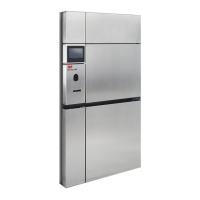
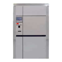
Steri-Vac Sterilizer/Aerator GS Series
Site Planning and Installation Guide
70-2011-5643-0 Issue Date: 10/2015
ANNEX C Site Readiness and Installation Verification Forms
Site Readiness Verification Form: 3M
™
Steri-Vac
™
Sterilizer/Aerator GS Series
Note: The following
form must be completed
by the purchaser facility
prior to scheduling the
installation support
service visit by 3M
Health Care service
personnel or authorized
3M service personnel.
Facility Name:
Address:
City: State/Province:
Country: ZIP/Post Code:
Contact Person:
3M Representative:
General
1. All national, state and local regulations related to the use of Ethylene Oxide have been obtained and reviewed, and the
requirements met.
Yes No
Electrical Supply
2. Enter the supply circuit current rating (15–20 amps).
Amps
3. Minimum supply voltage is greater than 200 volts (200–240 VAC, 50/60 Hz single phase).
Enter supply voltage.
Yes
Supply Voltage
No
VAC
Compressed Air
4. The compressor is labeled to verify the air supply is clean, with a maximum allowable dirt particle size of 0.5 microns, and free
of oil and is dry to 10°C (50°F) dew point at 38°C (100°F) ambient.
Yes No
5. The supply pressure is 7.0 kg/cm
2
(100 psig) minimum to 10.5 kg/cm
2
(150 psig) maximum.
Yes No
6. The air flow rate is 2.2 liters per second at 5.6 kg/cm
2
(4.7 cubic feet per minute at 80 psig) per sterilizer/aerator based on
100% duty cycle compressor.
Yes No
7. The volume of the air tank is adequate to meet the demand of all equipment used by the same air compressor.
Yes No
Venting
8. The vent line goes from the GS Series sterilizer to the outside atmosphere directly without being terminated into any existing
recirculating air flow system or ventilation system.
Yes No
9. The vent line is a hard drawn copper tube.
Yes No
10. Enter the total linear length of the vent line from the GS Series sterilizer to the termination point on the outside of the building.
10a. If the answer to Question 10 is greater than 91 m (300 ft), has the system been approved by 3M?
m / ft. CIRCLE UNIT
Yes No N/A
11. Enter the outside diameter of the vent line.
cm / in. CIRCLE UNIT
12. The vent line termination is located more than 7.6 m (25 ft.) from any possible sources of ignition or any openings to the building
(e.g., doors, fresh air intakes, unsealed windows, pedestrian walkways).
Yes No
13. The vent line is gas tight.
Yes No
14. If the vent line
extends outside of
the building:
a. The vent line is insulated to protect from freezing (where required).
b. There is a 180° downward bend at the end for the vent line if a vertical installation.
c. There is a 90° downward bend at the end for the vent line if a horizontal installation.
Yes No N/A
Yes
No N/A
Yes No N/A
Local Exhaust System (only applicable when the local exhaust hood is connected and operating)
15. The local exhaust system meets the air flow requirements stated in the exhaust ventilation specifications in the 3M Site
Planning and Installation Guide.
Yes No
16. The flow rate at the end of the facility exhaust duct at the sterilizer hood is from 59 to 66 L/sec (125 to 140 cfm) for a single
door unit or 118 to 132 L/sec (250) to 280 cfm for a double door unit.
Yes No
17. The ductwork material is impervious to EO (galvanized metal or SST).
Yes No
18. The local exhaust system termination is located more than 7.6 m (25 ft.) from any openings to the building.
Yes No
19. The exhaust hood blower is suitable for continuous operation and protected from adverse weather.
Yes No
I certify that I have assessed the above conditions and all have been met.
Facility Representative (print): Date:
Facility Representative (signature):
48
 Loading...