TroubleshootingGuide
30|Page
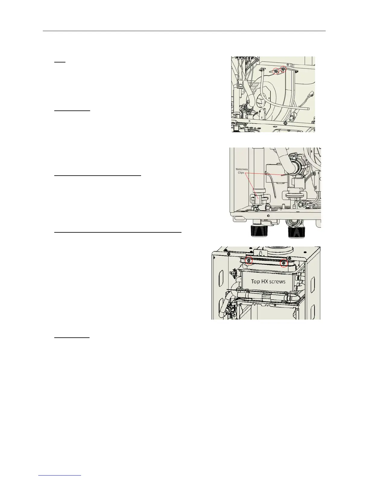
5) FAN
a. Thefanisheldinbytwoscrews.Theyfacethebottomof
theheater,andcanbereachedbytwoholesinthebottom
ofthecasewithalongscrewdriver.
b. Slideitlefttoreleaseitfromthegrooves.
6) WATERWAYS
a. Iftheunithasnotbeendrainedatthispoint,nowisthe
timetodoso.RefertotheDrainingtheUnitprocedurein
thetroubleshootingproceduressection.
b. Disconnectthewaterwayclipspicturedattheright.
c. Placeadry towelinthebottomoftheunit
casewhen
dislodgingthepipesfromtheirsockets.
7) REMOVETHEHEATEXCHANGER
a. Removethetwoscrewsatthetopoftheheatexchanger.
b. Theheatexchangershouldbefreetoberemoved.If
thereareanymissedwiresstillconnectedtotheheat
exchangerassembly,removethemsotheheatexchanger
iscompletelyfree.
8) REPLACETHEHEATEXCHANGERCOMPONENTS
a. Removeandinspectthenewheatexchangermakingsure
itisdesignedforthecorrectmodelandisnot
damagedatall.
b. Installthefollowingitemsfromtheold
exchangerontothenewone:
i. OverheatCutoffFuse
ii. Freezeprotectionblocks
iii. Plasticpressureport
iv. Hi‐
Limitswitch
v. Hotwaterthermistor
vi. SiliconVentGasket
9) REASSEMBLE
‐Reassembletheunitinreverseorder.Keypointstoremember:
a. Allwiresmustbereconnected.K eepwiresdanglingoutinfrontoftheunit,neverpushthem
towardthebackwheretheyarenotvisible;youwillforgetaboutthem.
b. Inspectallofthegaskets.
c. Beaware
ofthevariousO‐ringsonthegasandwatervalves,alongwiththewaterwayclips.
d. Reattachallextracomponentsthatthemanifoldscrewssecureintheirplaces.
e. Donothaveanyscrewsleftover.
Figure31
Figure32
Figure33