EasyManua.ls Logo

A.O. Smith 400 User Manual

A.O. Smith 400
48 pages
To Next Page IconTo Next Page
Page #1 background imageLoading...
Page #1 background image
1
PRINTED IN U.S.A. 0906
COPPER BOILERS FOR
HYDRONIC HEATING AND
HOT WATER SUPPLY
CAUTION
TEXT PRINTED OR OUTLINED IN RED CONTAINS
INFORMATION RELATIVE TO YOUR SAFETY.
PLEASE READ THOROUGHLY BEFORE INSTALLING
AND USING THIS APPLIANCE.
212511-000
MC BEE, SC., RENTON, WA.,
STRATFORD-ONTARIO, VELDHOVEN-THE NETHERLANDS,
NANJING, CHINA
www.hotwater.com / email:parts@hotwater.com
PLACE THESE INSTRUCTIONS ADJACENT TO BOILER AND
NOTIFY OWNER TO KEEP FOR FUTURE REFERENCE.
Installation
Operation
Maintenance
Limited Warranty
Instruction Manual
GB/GW MODELS:
1000, 1300, 1500, 1850, 2100, 2500
SERIES: 400, 401, 402, 403, 404, 405
WARNING: If the information in this
manual is not followed exactly, a fire or
explosion may result causing property
damage, personal injury or loss of life.
Thank You
for buying this cost
efficient, high recovery unit from
A. O. Smith Water Products Co.
You should thoroughly read and understand this
manual before installation and/or operation of this
boiler. Please pay particular attention to the
important safety and operating instructions as well
as the WARNINGS and CAUTIONS.
CONTENTS PAGE
DIMENSIONS/CAPACITIES DATA .......................... 2 - 3
FOREWORD......................................................... 4 - 5
FEATURES/CONTROLS ..................................... 5 - 7
INSTALLATION INSTRUCTIONS ....................... 7 - 9
VENTING ........................................................... 9 - 11
SYSTEM INSTALLATION ................................ 11 - 16
HYDRONIC INSTALLATION ............................ 16 - 18
HOT WATER SUPPLY INSTALLATION ........... 18 - 31
GAS CONNECTIONS...................................... 18 - 23
OPERATION .................................................... 31 - 34
LIGHTING AND OPERATING .......................... 32 - 33
CONTROL SYSTEM ....................................... 34 - 44
PREVENTATIVE MAINTENANCE.................. 44 - 46
TROUBLE SHOOTING .................................... 42 - 44
WIRING DIAGRAM/SCHEMATIC ................... 24 - 27
LIMITED WARRANTY ............................................. 47
Do not store or use gasoline or other
flammable vapors and liquids in the
vicinity of this or any other appliance.
WHAT TO DO IF YOU SMELL GAS:
Extinguish any open flame.
Do not try to light any appliance.
Do not touch any electrical switch; do
not use any phone in your building.
Immediately call your gas supplier
from a neighbor's phone. Follow the
gas supplier's instructions.
If you cannot reach your gas supplier,
call the fire department.
Installation and service must be
performed by a qualified installer,
service agency or the gas supplier.
Question and Answer IconNeed help?

Do you have a question about the A.O. Smith 400 and is the answer not in the manual?

A.O. Smith 400 Specifications

General IconGeneral
BrandA.O. Smith
Model400
CategoryBoiler
LanguageEnglish

Summary

Instruction Manual

Safety Warnings and Precautions

Key safety alerts regarding installation, operation, fire, and explosions.

Dimensions and Capacities Data

Gas and Electrical Requirements

Specifications for gas type, pressure, voltage, and amperage.

Dimensional Data Tables

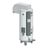
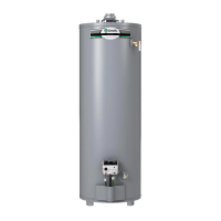
Detailed physical dimensions for various boiler models.

Foreword

Installation Guidance and Codes

Information on diagrams, piping methods, and code compliance.

Installation and Operation Basics

Grounding and Altitude Requirements

Proper electrical grounding and high altitude installation procedures.

Boiler Features and Controls

Overview of the multi-stage firing and control system components.

Boiler Controls and Safety Features

Pressure, Flow, and Limit Controls

Function of differential pressure, blocked flue, water flow, and limit controls.

Ignition and Safety Sensors

Role of flame sensor, igniter, and safety shut-off devices.

Pump and Water Level Control

Information on the circulating pump and low water cutoff devices.

Safety Relief Valves and Installation Location

Safety Relief Valve Requirements

Proper installation, function, and types of safety relief valves.

Boiler Installation Location

Guidelines for selecting an appropriate and safe installation location.

Installation Clearances and Air Supply

Service Clearances and Air Supply

Recommended space for servicing and ensuring adequate combustion air.

Confined and Unconfined Spaces

Requirements for air supply in different installation spaces.

Venting Systems

Standard Vertical Venting (Category I)

Requirements for Category I vertical venting installations.

Standard Horizontal Venting (Category III)

Requirements for Category III horizontal venting installations.

Direct Venting Options

Procedures for direct vent vertical and horizontal installations.

System Installation Procedures

Intake and Exhaust Termination

Guidelines for proper termination of intake and exhaust vents.

General System Installation

Best practices for filling, piping, and boiler replacement.

Hydronic Installation

Hydronic System Components

Description of required equipment for hydronic heating systems.

Space Heating Applications

Controlling hydronic systems for space heating and cooling.

Hot Water Supply Boiler Installation

Water Connections and Hard Water

Connecting water lines and addressing hard water issues.

Gas Connections and Safety

Critical safety and installation guidelines for gas supply.

Gas Piping and Electrical Connections

Gas Supply Line Sizing

Guidelines for correctly sizing gas supply lines.

Electrical Wiring Requirements

Compliance with electrical codes and safe wiring practices.

Gas Manifold Assembly

Manifold Diagrams by Model

Visual representation of gas manifold configurations for different boiler models.

Wiring Diagram

Series 400 Wiring Schematic

Detailed electrical schematic for the GB/GW 1000-2500 Series 400.

Control System Components and Configuration

CCB and FCB Dipswitch Functions

Configuration settings for Central and Flame Control Boards via dipswitches.

Schematic Diagram

Genesis GB/GW System Schematic

Overall schematic illustrating component interconnections and flow.

CCB Central Control Board Diagram

CCB Component Layout

Detailed layout of components on the Central Control Board.

FCB Flame Control Board Diagram

FCB Component Layout

Detailed layout of components on the Flame Control Board.

PDB Power Distribution Board Diagram

PDB Component Layout

Detailed layout of components on the Power Distribution Board.

Operation and System Filling

Fuse Protection and System Filling

Information on fuses, replacement, and procedures for filling water systems.

Gas Line Purging and Pressure

Safety and procedures for purging gas lines and checking inlet pressure.

Operating and Lighting Instructions

Safety Before Operation

Critical safety warnings and procedures before lighting the appliance.

Boiler Operating Instructions

Step-by-step guide for starting and operating the boiler.

Turning Off Gas to Appliance

Procedure for safely shutting off the gas supply to the unit.

Manifold Pressure and Control System

Manifold Pressure and Adjustments

Measuring and adjusting gas manifold pressure for optimal performance.

Control System Overview

Introduction to the EMC 5000 electronic control system and its functions.

Control System Inputs and Outputs

System Inputs (Sensors)

Description of various sensor inputs for system monitoring.

System Outputs (Relays)

Description of output signals controlling pumps, valves, and blowers.

Dipswitch Configuration

CCB and FCB Dipswitch Settings

How to configure the CCB and FCB using dipswitches for boiler operation.

Operating Sequence and FCB Configuration

FCB Dipswitch Settings

Configuring the Flame Control Board for specific functions like blower and igniter.

Boiler Operating Sequence

Step-by-step process of boiler startup, heating, and post-purge cycles.

User Interface Module (UIM) and Settings

UIM Navigation and Screens

How to navigate the UIM display and use touch switches for operation.

Temperature Setpoints

Adjusting operating, differential, and high limit temperature setpoints.

System Status and Control States

System Status Screen

Viewing real-time status of system inputs and output states.

CCB Control States

Understanding the different operational states of the Central Control Board.

Control States and User Settings

FCB Control States

Understanding the operational states of the Flame Control Boards.

User Settings Screen

Accessing and modifying user-configurable system parameters.

Setpoint Adjustments and System Information

Setpoint Adjustment Procedures

Step-by-step guides for adjusting operating and limit setpoints.

System Information Screens

Accessing log data, error history, and configuration settings.

Troubleshooting and User Interface

Error Screens and UIM Navigation

Navigating error screens and using UIM keys for troubleshooting.

Fault Messages and Troubleshooting

Identifying and resolving system faults using fault messages.

Preventative Maintenance

Main Burner and Flame Checks

Routine maintenance for burners, flame characteristics, and orifices.

Maintenance Procedures

Venting and Heat Exchanger Maintenance

Procedures for cleaning vents and heat exchangers to ensure efficiency.

Component Cleaning and Replacement

Tube Cleaning and Parts

Mechanical cleaning of tubes and information on ordering replacement parts.

New Boiler Limited Warranty

Warranty Terms, Conditions, and Claims

Details of warranty coverage, conditions, exceptions, and claim procedures.

Related product manuals