1
3
4
2 5
6
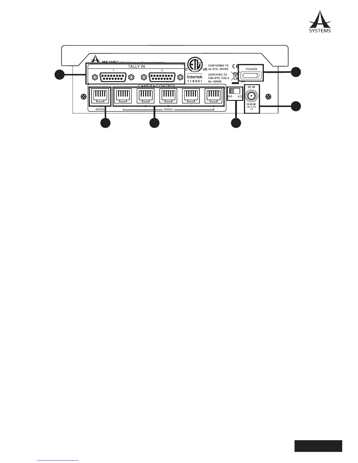
1. Tally Inputs (From video switcher)
a. Tally 1: PVW and PGM Tally signals input of Channel 1 to 5.
b. Tally 2: PVW and PGM Tally signals input of Channel 6 to 10.
2. RS485 Control Communication Port: Camera 1 to 5 control communication in Daisy-Chain
mode.
3. RS422 Control Communication Ports (1 to 5): Camera 1 to 5 communication in point-to-point
mode.
4. Power Switch
5. Communication Port Select Switch: Select control communication mode (RS422 or RS485).
To switch from one communication mode to another, after selecting the communication mode,
user must reboot the console for it to take effect.
6. DC Power Jack.