2-19
Chapter 2: Motherboard information
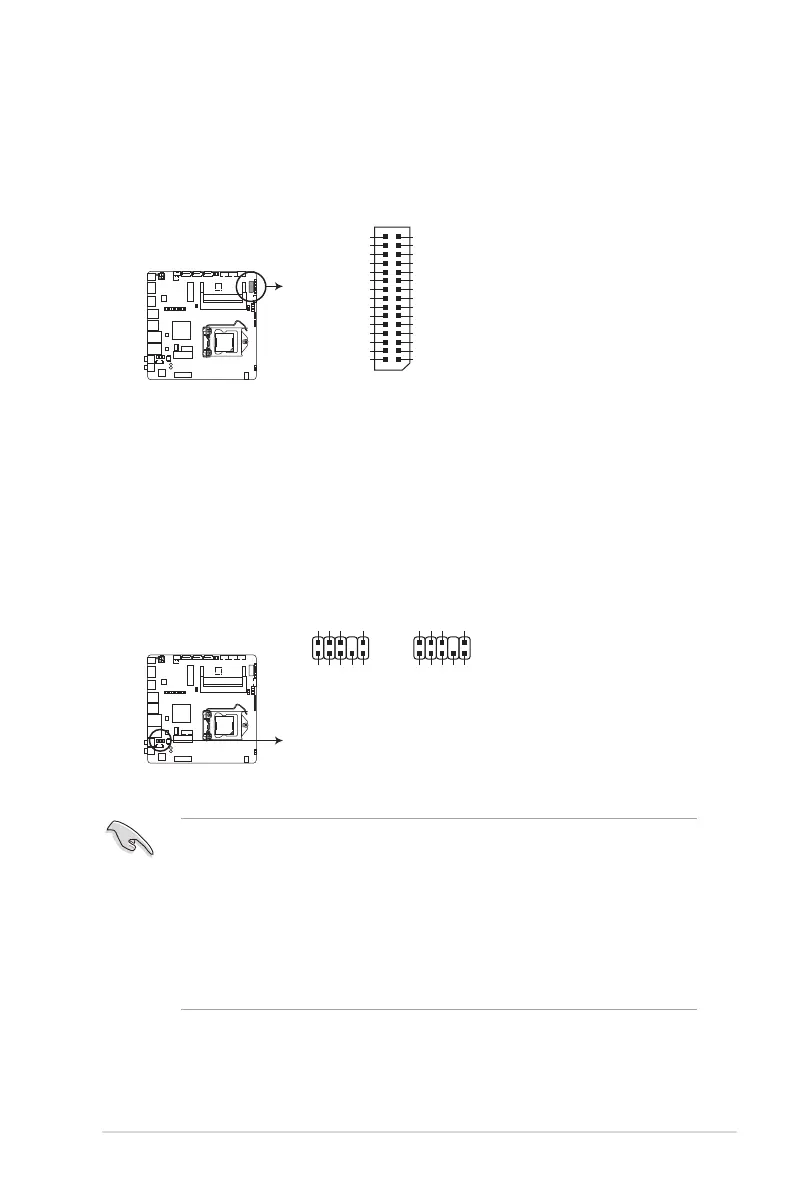
6. LVDS connector (30-pin LVDS)
ThisconnectorisforanLCDmonitorthatsupportsLowVoltageDifferential
Signalling(LVDS)interface.
7. Front panel audio connector (10-1 pin AAFP)
Thisconnectorisforachassis-mountedfrontpanelaudioI/Omodulethat
supportseitherHDAudioorlegacyAC`97audiostandard.Connectoneend
ofthefrontpanelaudioI/Omodulecabletothisconnector.
IMPORTANT!
• Werecommendthatyouconnectahigh-denitionfrontpanelaudio
moduletothisconnectortoavailofthemotherboard’shigh-denitionaudio
capability.
• Ifyouwanttoconnectahigh-denitionfrontpanelaudiomoduletothis
connector,settheFrontPanelTypeitemintheBIOSsetupto[HD];ifyou
wanttoconnectanAC’97frontpanelaudiomoduletothisconnector,set
theitemto[AC97].Bydefault,thisconnectorissetto[HD].
EMB-H81B LVDS Panel Signal connector
LVDS
PIN 1
LVDS1_CLK+
LVDS1_CLK-
GND
LVDS1_D3+
LVDS1_D3-
EDID_Clk (Unused)
LVDS1_D2+
LVDS1_D2-
GND
LVDS1_D1+
LVDS1_D1-
GND
LVDS1_D0+
LVDS1_D0-
Back Light Control
LVDS0_CLK+
LVDS0_CLK-
LVDS VCC
LVDS0_D3+
LVDS0_D3-
EDID_Data (Unused)
LVDS0_D2+
LVDS0_D2-
LVDS VCC
LVDS0_D1+
LVDS0_D1-
LVDS VCC
LVDS0_D0+
LVDS0_D0-
LVDS Panel Enable
EMB-H81B Front panel audio connector
AAFP
AGND
NC
SENSE1_RETUR
SENSE2_RETUR
PORT1 L
PORT1 R
PORT2 R
SENSE_SEND
PORT2 L
HD-audio-compliant
pin definition
PIN 1
AGND
NC
NC
NC
MIC2
MICPWR
Line out_R
NC
Line out_L
Legacy AC’97
compliant pin definition
PIN 1
 Loading...