Do you have a question about the Aaeon PCM-5896 and is the answer not in the manual?
Details the technical specifications of the SBC, including CPU, memory, I/O, and interfaces.
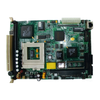
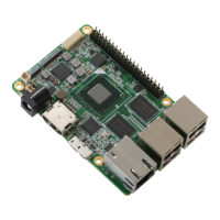
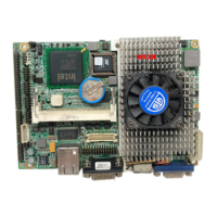
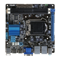
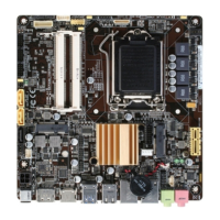
Visual diagram showing the physical arrangement of components on the mainboard.
Technical drawing with measurements for the mainboard's physical size.
Lists and describes the functions of various jumpers and connectors on the motherboard.
Identifies the physical location of key components like jumpers and connectors on the motherboard.
Explains how to configure the system by correctly setting jumpers.
Step-by-step guide for installing the CPU and Single Inline Memory Modules (DIMMs).
Details on configuring system settings via jumpers for CMOS, COM ports, LCD, and CPU.
Instructions for connecting power, USB, IDE, Floppy, Serial, Ethernet, and Display devices.
Guide for installing the DiskOnChip solid-state flash disk.
How to enter the BIOS utility and use keyboard shortcuts for navigation.
Overview of main BIOS setup sections like Standard CMOS, Features, Chipset, and Power Management.
Configuration of basic system settings like date, time, and hard disk drives.
Advanced BIOS options for system performance and features.
Settings related to the system chipset, memory, and bus speeds.
Configuration options for system power saving modes.
Configuration of onboard devices like IDE, USB, serial, and parallel ports.
Setting system passwords and using the IDE HDD auto detection utility.
How to save changes and exit the BIOS setup utility.
Information on display drivers, hardware configuration, and prerequisites for installation.
Step-by-step instructions for installing display drivers on Windows 95, 3.1, NT 3.51, and NT 4.0.
Instructions for installing display drivers on OS/2 operating systems.
Guide to configuring the onboard Ethernet interface and running diagnostics.
Description of the PCM-5896's audio capabilities and compatibility.
Step-by-step guide for installing audio drivers on Windows 95 and Windows NT.
Details on how to set the time-out interval and event for the watchdog timer.
Example code demonstrating the usage of the watchdog timer.
Step-by-step instructions for mounting PC/104 expansion modules.
List of cables included in the PCM-10489-4 wiring kit.
Information on available optional USB cables and their compatibility.
| Max Memory | 32 GB |
|---|---|
| Power Supply | 12V DC |
| Memory Slots | 1 x SODIMM |
| I/O Interface | 1 x RS-232/422/485 |
| Display Output | HDMI, VGA |
| Operating Temperature | 0°C to 60°C |
| USB Ports | 4 x USB 3.0 |