17
Plug (Provided)
Hirose Electric
Plug unit (Soldered type)
Note: The products above are subject to be replaced with the equivalent.
Cable
Note: Use a shielded cable. Connect the shield to the connector case.
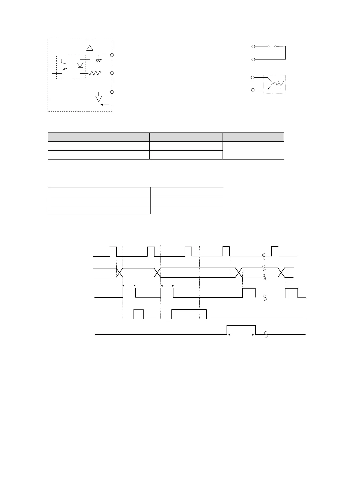
I/O timing chart
The factory setting of Tstr (Strobe pulse width) is approx. 10 msec. The BCD data should be
acquired approximately 5 msec after the strobe changes from ON to OFF.
* - “All input pins ON”, is the condition, where all input signals are connected to GND (Pin 3).
- When inputting RE-ZERO for 100 msec, the weighing instrument maintains the re-zero state.
ON
OFF
1
0
O
N
OF
F
ON
O
FF
Ts
tr
Tst
r
1
00
mse
c
Af
te
r
R
E-
ZE
R
O
O
N
OFF
Re
ceiv
e d
ata
(RS-2
32C
)
BCD o
utpu
t
S
TROBE
BU
SY*
R
E
-
ZE
R
O*
Balanc
e
in
t
er
io
r
I
np
u
t
si
g
na
l
G
ND
3
+5V
4.7
kΩ
Housing (Cable shield)
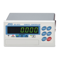
When a photocoupler is used
In
put terminal
(Upon sw
it
ch
-
ON
,
m
ak
e
t
he
vo
lt
a
ge
between the input terminal and t
he
input signal GND terminal 0.2V or
les
s)
When a switch is used
(1)
(2)
5, 9, 7 pin
Input signal GND
FG
FG
R
E-
ZE
RO, ON/OFF, BUSY
5, 9, 7 pin
Input
s
ig
n
al
G
N
D