16
6. BCD OUTPUT CONNECTOR
Outputs the weighing data received from the weighing instrument in BCD format, along with the polarity
(+/-) and the data status (stable/unstable and over (E display)).
Using the STROBE signal, the data can be read easily. BUSY input enables the data to be held or
prevents data refreshing during the reading operation.
Contact inputs are RE-ZERO and ON/OFF. They have same function as the key switches on the front panel.
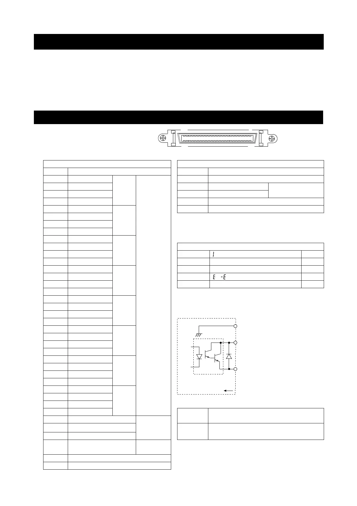
6.1. Connector Pin No and Specifications
I/O connector of the rear panel
Pin assignments and I/O logic
10
0
Data
Switch
10
1
- The pins, which are not specified, have no
connection. (2, 4, 6, 8, 10, 36, 38 pin)
10
2
Output logic (Factory settings)
10
3
Stabilization indicator ON
* When changing OFF ON, replaces the data.
10
4
- All output, open collector; withstand voltage 30 V;
no pull-up resistor; low-level output current 10 mA
10
5
10
6
10
7
BUSY
Data will be held during ON
(when connected to input signal GND).
Status
Stability
Switch will be performed with ON
(when connected to input signal GND).
43 Strobe
- All input, no voltage contact or open collector
(connected to 5 V internally)
Ba
lan
ce
interior
0
7
Output pins
BCD
signals
Pin 1
BCD signals
(Data from 10 -1 to 10 -8, Polarity,
Stability, OVER, Status, Strobe)
Output signal GND
Use a shielded cable.
Housing (Cable shield)
FG