11MHGRVX-B2 Module Technical Guide
OPERATION MODES
Modes of Operation
Initialization
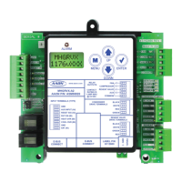
The MHGRVX-B2 uses on-board LEDs to indicate various
diagnostic conditions during power-up and operation. It also uses an
LCD display to show initialization. Please review this information
for a complete description of the initialization sequence.
Modulating Hot Gas Valves
The MHGRVX-B2 utilizes two modulating valves to control the ow
of Hot Gas through the Hot Gas Reheat Coil. One of these valves is
the Condenser Hot Gas Valve and the other is the Hot Gas Reheat
Valve. The valves are wired to the MHGRVX-B2 Modulating Hot
Gas Valve Output terminals. These valves work in concert with each
other to create a “three-way valve” conguration. As one closes, the
other opens, etc. All modes of operation that follow referring to the
Hot Gas Reheat Valve are actually a combination of these two valves
working together to achieve the specied sequence of operation.
NOTE: Some units use a three-way valve instead of two
separate valves. The three way valve is wired to the
Reheat terminal block.
Modes of Operation
The MHGRVX-B2 can be used in two dierent modes of operation.
These modes behave in a similar manner; the main dierence is
the way they receive information to control the dehumidication
process.
Stand-Alone Mode
As the name implies, in this mode the module behaves as an
independent unit. The module begins the dehumidication process
when the Dehumidication Input “H1” receives a 24 VAC signal
from an outside source. When the signal is received, the module will
activate the “FAN” output to energize the HVAC unit fan. At the
same time, the module will initiate Cooling Mode by energizing the
“CMP” output starting the HVAC unit compressor. At this time, the
MHGRVX-B2 will start to modulate the Modulating Hot Gas Reheat
Valve. The module will modulate the MHGR valve to maintain the
Supply Air Temperature Setpoint by activating the stepper motor
outputs on the MHGR Valve.
The Supply Air Setpoint is congured with the Setpoint Screen in
the LCD display. If Supply Air Temperature Reset is used, it will
initiate when a 0-10 VDC signal is supplied to the “RESET IN”
input. As the voltage increases from 0 to 10 volts at the “RESET IN”
input, the Supply Air Temperature will be reset towards the Supply
Air Reset Temperature Setpoint. This setpoint is congured with the
Setpoint Screen in the LCD display. When a 10-volt input signal
is received at the “RESET IN” input, it will be controlling at the
Supply Air Temperature Reset Setpoint. The controller will conclude
the Dehumidication process when input “H1” is deactivated, the
input “Cool Override” is activated, or the input “Heat Override”
is activated.
Auxiliary Mode Stand-Alone
1. Auxiliary Mode Operation needs to be congured rst
from the display.
2. This mode will be activated if the Reheat Enable input
is enabled. Any expansion boards that are enabled will
follow.
3. Reheat Valve
• The unit will keep the valve o for the rst 30 seconds
• Then it will modulate the valve between 0% to 100%
to match the 0-10 VDC Auxiliary Analog input.
4. The unit will exit Reheat Mode when the reheat input
is disabled. The expansion modules will do the same.
5. Relay Operation
• Fan Relay will be activated in this mode.
• Compressor Relay will be activated in this mode.
• Auxiliary Relay
○ It will be activated if the Reheat Valve stays at 100%
for two minutes and the Supply Air Temperature is
5°F below the Supply Air Setpoint.
○ It will deactivate if the Reheat Valve stays at 0% for
two minutes and the Supply Air Temperature is 5°F
above the Supply Air Setpoint.