6MHGRVX-B2 Module Technical Guide
WIRING
Installation and Wiring
Installation and Mounting
The MHGRVX-B2 is housed in a plastic enclosure. It is designed
to be mounted by using the three mounting holes in the enclosure
base. It is important to mount the module in a location that is free
from extreme high or low temperatures, moisture, dust, and dirt. Be
careful not to damage the electronic components when mounting
the module.
NOTE: The MHGRVX-B2 contains no user-serviceable
parts. Contact qualied technical personnel if your
controller or module is not operating correctly.
Wiring
The modules must be connected to an 18-30 VAC power source
of the proper size for the calculated VA load requirements. All
transformer sizing should be based on the VA ratings listed in Table
1, this page.
NOTE: If the temperature at the MHGRVX-B2 is below
-4ºF (-20ºC), the display refresh rate could be less
responsive.
WARNING: When using a single transformer to power more
than one controller, module, or expansion
module, the correct polarity must always be
maintained between the boards. Failure to
observe correct polarity will result in damage
to the unit controller, MHGRVX-B2, and any
associated modules.
Please carefully read and apply the following information when
wiring the unit controller, MHGRVX-B2 and any associated module.
1. All wiring is to be in accordance with local and national
electrical codes and specications.
2. All 24 VAC wiring must be connected so that all ground
wires remain common. Failure to follow this procedure
can result in damage to the controller and connected
devices.
3. Minimum wire size for 24 VAC wiring should be
18-gauge.
4. Minimum wire size for all sensors should be 24-gauge.
Some sensors require two-conductor wire and some
require three-or four-conductor wire.
5. Minimum wire size for 24 VAC thermostat wiring should
be 22-gauge.
6. Be sure that all wiring connections are properly inserted
and tightened into the terminal blocks. Do not allow wire
strands to stick out and touch adjoining terminals which
could potentially cause a short circuit.
7. When communication wiring is to be used to interconnect
HVAC unit controllers together or to connect to other
communication devices, all wiring must be plenum-
rated, minimum 18-gauge, two-conductor, twisted pair
with shield. AAON can supply communication wire that
meets this specication and is color coded for the network
or local loop. Please consult your AAON distributor for
information. If desired, Belden #82760 or equivalent wire
may also be used.
8. Before applying power to the HVAC unit controller,
MHGRVX-B2, and any associated modules, be sure
to recheck all wiring connections and terminations
thoroughly.
Powering Up
When the controller and/or modules are rst powered up, the
POWER LED should light up and stay on continuously. If it does
not light up, check to be sure that you have 24 VAC connected to
the controller, that the wiring connections are tight, and that they are
wired for the correct polarity. The 24 VAC power must be connected
so that all ground wires remain common. If after making all these
checks, the POWER LED does not light up, please contact AAON
Controls Support for assistance.
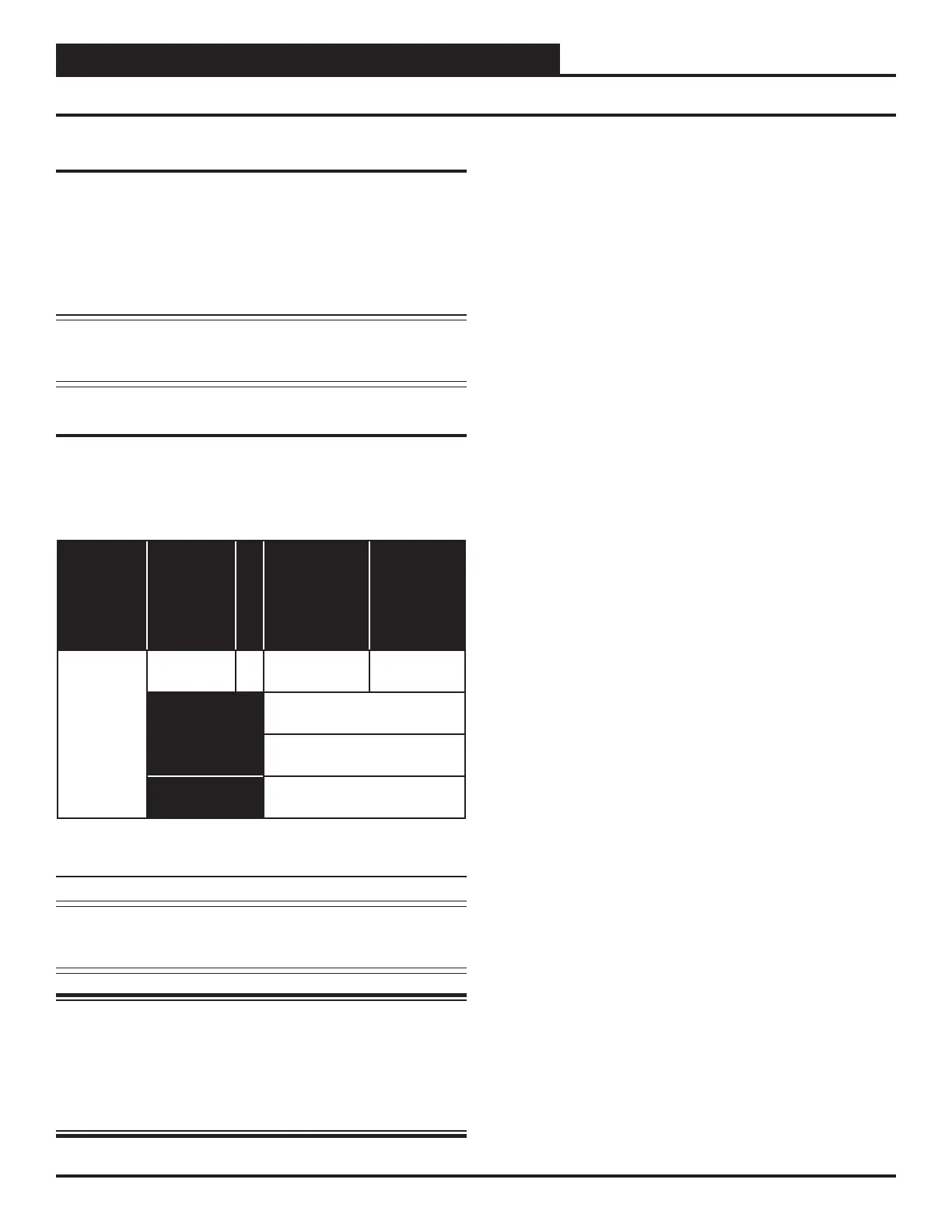
Control
Device
Voltage
VA Load
Operating
Temperature
Humidity
(Non-
Condensing)
MHGRVX-B2
18-30VAC 18
-22°F to 158°F*
-30ºC to 70ºC*
0-95% RH
Inputs
Resistive Inputs require 10KΩ
Type 3 Thermistor
24VAC Inputs provide 4.7KΩ
Load
Outputs
Relay Outputs: 1 Amp
maximum per output.
Table 1: MHGRVX-B2 Electrical and Environmental
Requirements