4MHGRVX-B2 Module Technical Guide
FIGURES AND TABLES
TABLES
Table 1: MHGRVX-B2 Electrical and Environmental Requirements ........................................................................ 6
Table 2: MHGRVX-B2 Inputs and Outputs .............................................................................................................. 9
Table 3: Navigation Key Functions ......................................................................................................................... 14
Table 4: STATUS LED Blink Codes ........................................................................................................................ 21
Table 5: ALARM LED Blink Codes ......................................................................................................................... 21
Table 6: 0-3V Temperature Sensor - Voltage and Resistance for Type III Sensors ............................................... 23
Table 7: 0-5V Temperature Sensor - Voltage and Resistance for Type III Sensors ............................................... 24
Table 8: SAT Wiring Conditions .............................................................................................................................. 26
Table 9: Reheat Expansion Module ALARM LED Blink Codes .............................................................................. 31
FIGURES
Figure 1: MHGRVX-B2 Dimensions ..........................................................................................................................5
Figure 2: MHGRVX-B2 to AAON Unit Controller Wiring ...........................................................................................7
Figure 3: MHGRVX-B2 Stand-Alone Wiring ..............................................................................................................8
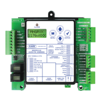
Figure 4: LCD Display and Navigation Keys ...........................................................................................................14
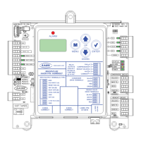
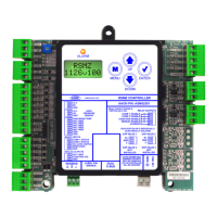
Figure 5: MHGRVX-B2 LED Locations and Descriptions ........................................................................................22
Figure 6: Supply Air Temperature Sensor Installation .............................................................................................25
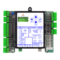
Figure 7: Reheat Expansion Module Dimensions ...................................................................................................27
Figure 8: Reheat Expansion Module(s) Wiring .......................................................................................................29
Figure 9: Reheat Expansion LED Locations and Descriptions ...............................................................................31