Full Digital Module
Technical Guide
14
Connect To
E-BUS
Distribution
Module
Line Voltage
24 VAC
GND
Line Voltage
All Comm Loop Wiring Is
Straight Thru
24VAC
GND
Local Loop
RS-485
9600 Baud
See Individual Component
Wiring Diagrams For
Detailed Wiring Of Analog
Inputs And Outputs
For Stand Alone Applications,
Connect To System Manager.
For Network Applications
Connect To Next Controller
And/Or MiniLink PD On Local Loop.
G - Fan ON/OFF Only
R - 24VAC
Relay Output Contacts
R2 Through R5 May Be User-Configured
For The Following:
1 - Heating Stages
2 - See Note 1 Below
3 - Warm-up Mode Command (VAV Boxes)
4 - Reversing Valve (Air To Air Heat Pumps)
5 - Reheat Control (Dehumidification)
6 - Exhaust Fan Interlock
7 - Preheater For Low Ambient Protection
8 - Alarm
9 - Override
10 - Occupied
11 - OA Damper
12 - Heat Wheel
13 - Emergency Heat
Note: 1.) When Using the HP2C Module,
All Compressors Will Be Wired From the
Protection Module, Not the VCM-X
Controller.
2.) A Total Of 20 Relays Are Available By
Adding Relay Expansion Modules. All
Expansion Module Relay Outputs Are User-
Configurable As Listed Above.
Connect FRP Tubing To High Pressure
Port (Bottom Tube) and Route To Static
Pressure Pickup Probe Located In Unit
Discharge. Leave Port Marked “Lo” Open
To Atmosphere
OE271
Static Pressure
Transducer
Splice If Required
Connect To E-BUS Distribution Module
or Expansion Module(s) (When Used)
Connect To Digital Room Sensor And/Or
Digital CO Sensor
2
Warning:
24 VAC Must Be Connected So That All Ground
Wires Remain Common. Failure To Do So Will
Result In Damage To The Controllers.
T to T, R to R & SHLD to SHLD
Size Transformer For
Correct Total Load.
VCM-X Modular Controller
= 8 VA
OE332-23-VCMX-MOD-A
VCM-X Modular Controller
Note:
All Relay Outputs Are Normally Open And Rated
For 24 VAC Power Only.
1 Amp Maximum Load.
AI1
AI1 SET AI2 SET AI3 SET
AI4 SET AI5 SET AI7 SET
AI2
AI3
AI4
AI5
AI7
AI1 SET AI2 SET AI3 SET
AI4 SET AI5 SET AI7 SET
Jumpers
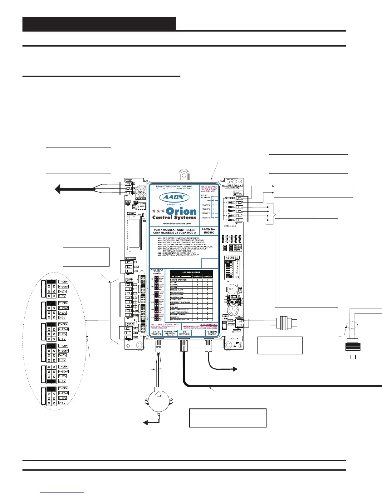
Figure 6: VCM-X Modular Controller Connection to Full Digital Module
Appendix
VCM-X Modular Controller to Full
Digital Module Wiring
When using the VCM-X Modular Controller, the E-BUS Distribution
Module is required ot connect to the Full Digital Module. The Full Digital
Module connects to the E-BUS Distribution Module using a modular
HSSC cable. The Full Digital Module requires a 24 VAC power con-
nection with an appropriate VA rating.
The E-BUS Distribution Module connects to the VCM-X Modular
Controller, VCM-X Expansion Module, or 12 Relay Expansion Module
using the I
2
C port. See Figure 6 below for wiring.
Any E-BUS module can be connected to each of the four E-BUS
Dis-
tribution Module’s output ports or can be daisy-chained together using
HSSC cables.
If using a spliced terminal connection for longer runs, one module can be
connected to the E-BUS Distribution Module and any additional modules
would be daisy-chained to the fi rst module. For more information, refer
to the E-BUS Distribution Module Technical Guide.
 Loading...


