Full Digital Module
Technical Guide
4
Environmental Requirements
The Full Digital Module needs to be installed in an environment which
can maintain a temperature range between -30°F and 150°F and not
exceed 90% RH levels (Non-Condensing).
Mounting
The Full Digital Module is housed in a plastic enclosure. It is designed
to be mounted by using the 3 mounting holes in the enclosure base. It is
important to mount the module in a location that is free from extreme high
or low temperatures, moisture, dust, and dirt. Be careful not to damage
the electronic components when mounting the module.
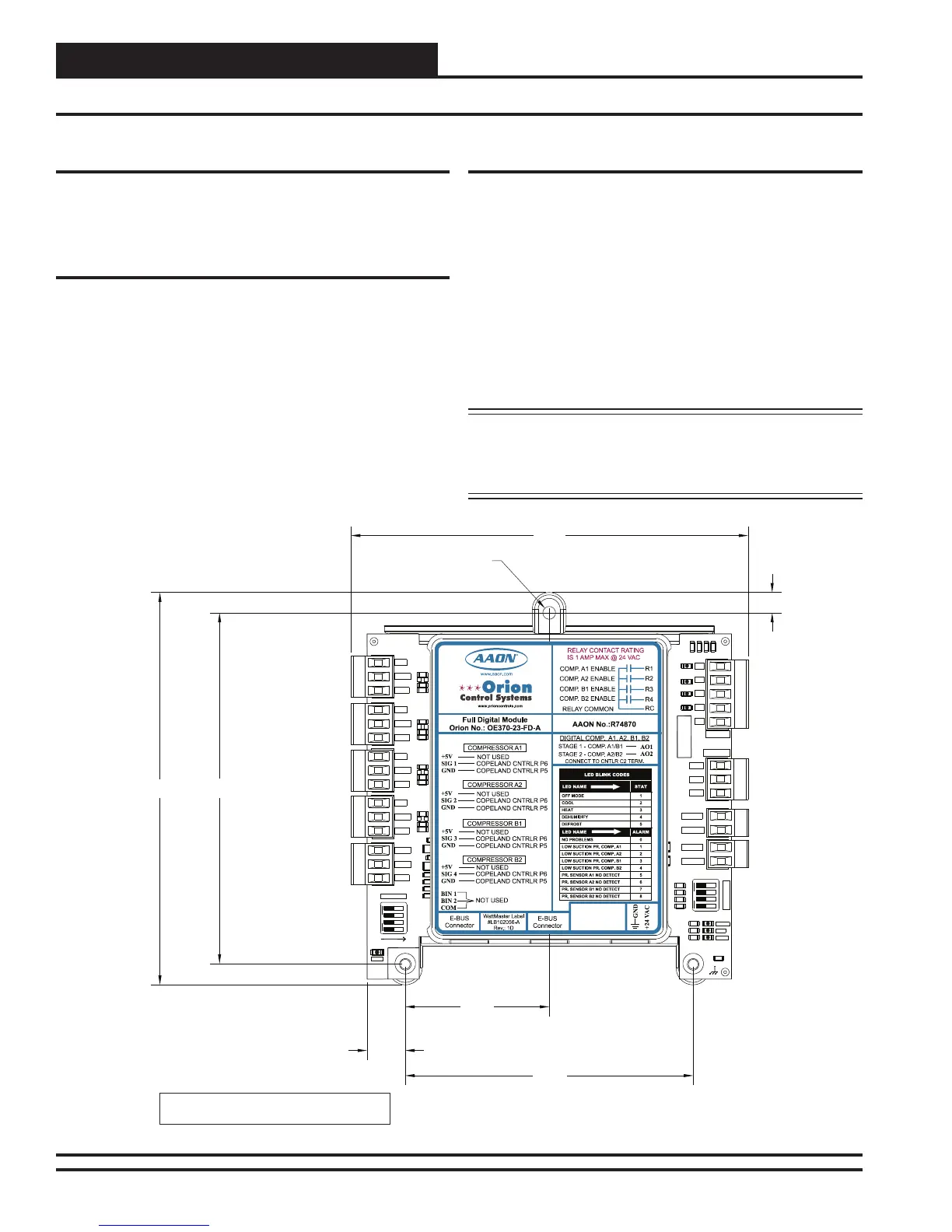
See Figure 2 for Module dimensions (dimensions are in inches).
Power Supply and Communications
The Full Digital Module is connected to the E-BUS Distribution Mod-
ule with a modular HSSC cable to provide communications from the
VCM-X Modular Controller. The E-BUS Distribution Module uses
WattMaster Control’s standard I
2
C modular cable to connect with the
VCM-X Modular Controller, VCM-X Expansion Module, or 12-Relay
Expansion Module.
The Full Digital Module can also be directly connected to the VCM-X
Modular E-BUS Controller, bypassing the use of the E-BUS Distribu-
tion Module.
The Full Digital Module requires a 24 VAC power supply with an ap-
propriate VA rating.
WARNING: Observe polarity! All boards must be wired
GND-to-GND and 24 VAC-to-VAC. Failure to
observe polarity could result in damage to the
boards.
Installation and Wiring
5.04
5.64
5.71
2.07
0.55
4.14
0.29
0.18 DIA. TYP.
www.orioncontrols.com
1003
1002
10uF
300
1
2
4
8
SERIAL #
C2
D3
D4
R7
R9
R11
R12
R13
R14
R23
R24
R25
R26
R28
R29
R30
SW1
D12
D13
R53
R54
TB3
C20
R34 R50
SW2
+5V
SIG 2
GND
1003
1002
10uF
1003
1002
10uF
1003
1002
10uF
4751
4751
4751
4751
OFF
OFF
OPTIONS
ALARM
ANALOG
STAT
+5V
COMM
GND
SIG 4
300
GND
BIN 2
R1
4
R2
4
GND
1002
1002
1002
1002
1002
1002
1002
1002
RELAYS
ADDRESS
SIG 3
+5V
GND
BIN 1
COM
+5V
SIG 1
R3
R4
Rc
AO1
AO2
PWM1-
PWM1+
PWM2-
PWM2+
.01uF
PWR
Note: Height is 1.49 inches.
Figure 2: Full Digital Module Dimensions