30
Purge Circuit
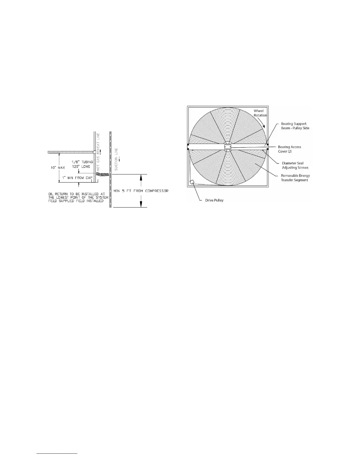
The purge circuit is required on hot gas reheat
or hot gas bypass lines. The purge circuit
needs to be field furnished and installed at the
lowest point of the line set.
With this installation, oil drains into the drain
leg of the hot gas reheat line. Oil accumulates
until it reaches the level of the 1/8”OD
capillary tubing.
The combination of capillary action and the
pressure difference between the hot gas
reheat line (high pressure) and the suction
line (low pressure) causes the oil to travel
through the capillary tube into the suction
line of the first circuit to return the oil to the
compressor. The capillary tube connection to
the suction line of the first circuit must be a
minimum of 5 feet from the inlet to the
compressor to allow the oil time to dissipate
into the suction vapor and not slug the
compressor with liquid oil.
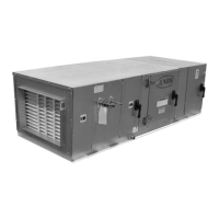
Energy Recovery Units
Some V3 units have been equipped with an
energy recovery wheel. This section is
provided to assure the energy recovery
feature will be properly setup to perform in
accordance with the job specifications for
your particular application.
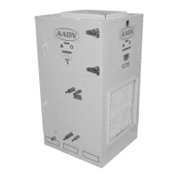
Figure 18 - Energy Recovery Wheel
The Energy Recovery Cassette consists of a
frame wheel, wheel drive system, and energy
transfer segments. Segments are removable
for cleaning or replacement. The segments
rotate through counter flowing exhaust and
outdoor air supply streams where they
transfer heat and/or water vapor from the
warm, moist air stream to the cooler and/or
drier air stream.
The initial setup and servicing of the energy
recovery wheel is very important to maintain
proper operation efficiency and building
occupant comfort.
Normal maintenance requires periodic
inspection of filters, the cassette wheel, drive
belts, air seals, wheel drive motor, and its
electrical connections.
Wiring diagrams are provided with each
motor. When wired according to wiring
diagram, motor rotates clockwise when
viewed from the shaft/pulley side.