60
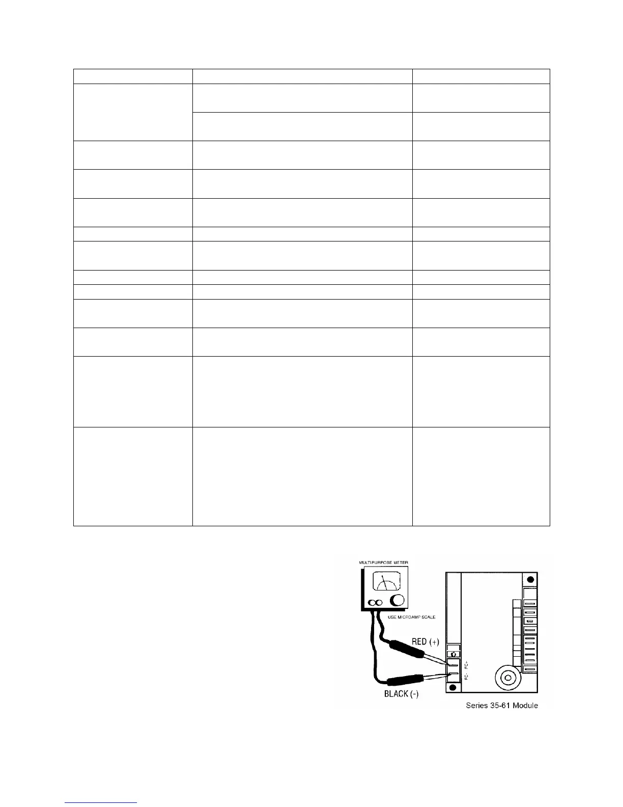
Table 18 - Ignition Control Sequence of Operation
Control verifies limit switches are closed
Flashes “4” if limit is
open
Control verifies the pressure switch is
open
Soft lock-out and flashes
“3” if switch is closed
Control verifies the pressure switch is
closed within 10 sec
Flashes “2” if switch is
open after 10 sec
No flame and pressure switch closed
Soft lock-out if flame is
present, flashes “5”
3 trials with 45 sec inter-purge period if it
doesn’t light in 10 sec
Soft lock-out, flashes “1”
alarm
Blower delay after ignition proof
Limit or pressure switch
faults
Inducer fan runs after heat call is removed
Time starts after heat call is removed
Re-tries 4 times if flame is lost
Soft lock-out if no
iginition, flashes “1”
Only sensed when heat call is present
Flashes “4” if limit is
open
Can be reset by removing heat call “W” or
power to control.
Soft lock-out may be caused by failed
ignition or too many flame losses.
Soft lock-out, flashes “1”
alarm
Controller issue, reset by removing power
to the control only.
Hard lock-out may be caused by internal
RAM or ROM corruption, faults in flame
sense circuit, or faults in gas valve drive
circuits.
Hard lock-out, status
LED de-energized
Service Checks
Flame current is the current which passes
through the flame from the sensor to ground.
The minimum flame current necessary to
keep the system from lockout is
0.5microamps. To measure flame current,
connect an analog DC microammeter to the
FC- and FC+ terminals per Figure 41. Meter
should read 0.5 uA or higher. If the meter
reads below “0” on scale, meter leads are
reversed. Disconnect power and reconnect
meter leads for proper polarity.
Figure 41 - Flame Sensor Current Check