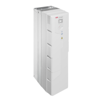
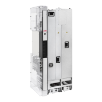
Drive control unitZCU/BCU
See the circuit diagrams delivered with the drive for the actual wiring and terminals. For
wiring diagram examples, see chapter Circuit diagrams.
Start-up and acceptance test
Use the Drive composer PC tool or a control panel to do the start-up and acceptance test.
To set FSO module parameters, you must use the Drive composer pro PC tool.
Action
Initial status
Make sure that the drive is ready for use, that is, you have done the tasks of the drive start-up procedure.
See the drive hardware manual.
WARNING!
Obey the Safety instructions (page 9). If you ignore them, injury or death, or damage to the
equipment can occur.
Checks and settings with no voltage connected
Stop the drive and do the steps in section Electrical safety precautions (page 11) before you start the
work.
Make sure that the classification of the motor thermal protection function corresponds to the Ex classi-
fication of the environment and the Ex motor.
The motor manufacturer selects the PTC sensors for the motor temperature measurement. Make sure
that the temperature on-off resistances match those of the PTC thermistor relay. Also make sure that
there is basic or reinforced insulation between the sensor and the motor main circuit.
Make sure that the installation of PTC sensors complies with the requirements for the applicable type
of protection. See section Wiring (page 24).
Make sure that the wires are connected to the correct terminals and that the terminal connections are
tightened.
Settings with voltage connected
If necessary, set the applicable parameters. See chapter Parameter settings (page 41).
If necessary, configure the motor overtemperature and STO indication. See section Reset method and
status indications (page 41).
Acceptance test procedure
To test short-circuit detection, short-circuit the sensor input with a 20 ohm resistance (you do not have
to disconnect the sensor circuit).
Expected outcome: Relay fault trip (the applicable LED lights). Drive STO is activated.
Make sure that the correct indications are activated.
To test wire break monitoring, disconnect the sensor circuit.
Expected outcome: Relay fault trip (the applicable LED lights). Drive STO is activated.
Make sure that the correct indications are activated.
To test excess temperature detection, increase the resistance of the sensor circuit from 50 … 1500 ohm
to 4 kohm.
Expected outcome: Relay fault trip (the applicable LED lights). Drive STO is activated.
Make sure that the correct indications are activated.
With the relay(s) in tripped state, try to start the drive. The drive must not start before the PTC relay(s)
and/or any drive (and FSO) faults are reset.
Fill in and sign the acceptance test report which verifies that the safety function is safe and accepted
to operation.
26 ATEX-certified motor thermal protection function with PTC thermistor relays (+L513+Q971)

 Loading...


