Device description Connections
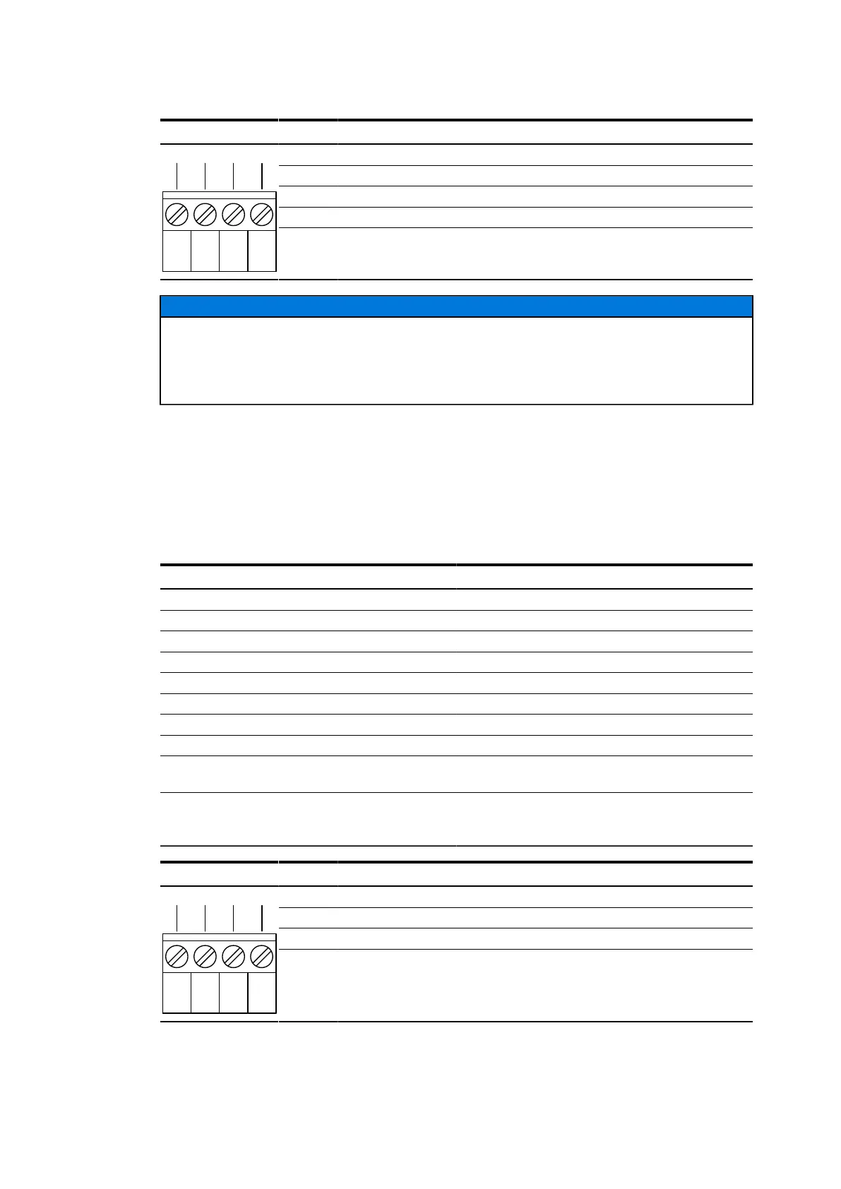
Pin allocation power supply (X1)
Pin Signal
1 24-60 V DC
2 Functional earth (internally wired to pin 4)
3 GND
1 2 3 4
4 Functional earth (internally wired to pin 2)
ADVICE
Due to the internal overvoltage protection, interrupt any connection to ground of the
device for the time of the measurement before you carry out isolation measurement. This
includes the earthing of the hat rail as well as all shields of all transmission lines and supply
feedings. RJ-12 plugs or RJ-45 plugs can establish earthing via the shield.
4.7.6 Alarm-Relay (X2)
The devices are equiped with a potential free alarm output (relay with isolated switchover
contact). This output corresponds to a device alarm and is activated when the device looses
the power supply or the alarm LED is constantly on (see Chapter 4.8, "Display elements"). The
reason for the signalling of an alarm can be referenced in the system alarm table (EDS500
Manual - Part 2: Alarms and alarm configuration).
Alarm output (X2)
Type of switch Toggle (potential free)
Switching voltage 60 VDC / 25 VAC
Switching current 500 mA
Plug type Phoenix Contact MSTBT 2,5/4-ST
Circuit classification SELV (acc. IEC 60950-1)
Overvoltage protection line to earth ±4 kV, line to line ±2 kV
Electrical fast transient / Burst, IEC 61000-4-4 4 kV (level 4), criterion A
Surge 1.2/50 µs, IEC 61000-4-5 4 kV (level 4), criterion A
Conducted disturbances, induced by radio-
frequency fields, IEC 61000-4-6
10 V (level 3), criterion A
Conducted, common mode disturbances
in the frequency range 0 Hz to 150 kHz,
IEC 61000-4-16
30 V continuous disturbance/ 300 V short
duration disturbance (level 4), criterion A
Pin allocation alarm output (X2)
Pin Signal
1 & 2 Normal state
1 & 3 Alarm state
1 2 3 4
4 Common contact (connected to 1)
1KGT150966 V0001 35