Do you have a question about the ABB 520ADD02 and is the answer not in the manual?
The 520ADD02 is an I/O adapter designed for use with RTU520 and RTU540 systems, facilitating the connection of I/O modules. It serves as a crucial component for expanding the I/O capabilities of these systems, supporting various configurations and communication protocols.
The I/O adapter 520ADD02 is used to connect more than 16 RTU520 I/O modules to an I/O bus with RS485 or fiber optic connection in RTU520 or RTU540. This adapter extends the WRB I/O bus for decentralized I/O applications up to 2 km distance and allows for more than 30 cm between the I/O adapters. In addition, the I/O adapter 520ADD02 can be used as a stand-alone module to connect RTU560 I/O modules (e.g., 23BE40, 23BE50, 23BA40) to an RTU540.
The I/O adapter is connected to the WRB I/O bus (wired OR bus) and generates the addresses for the connected I/O modules within the I/O assembly automatically. The I/O adapter is always the last adapter unit within the virtual I/O rack 1. It converts the WRB I/O bus to the SPB I/O bus (serial peripheral bus) with electrical RS485 or fiber optical connection.
The module is available in two versions (rubrics):
The 520ADD02 supports various addressing modes, including 8/8, 8/0, 4/4/4/4, and 4/4/4/0, depending on the I/O assembly configuration. The addressing mode 8/8 allows for 8 I/O modules per I/O assembly, maximum 2 I/O assemblies per virtual I/O rack. The 8/0 mode supports 8 I/O modules per I/O assembly, maximum 2 I/O assemblies per virtual I/O rack (not used with RTU520). The 4/4/4/4 mode supports 4 I/O modules per I/O assembly, maximum 4 I/O assemblies per virtual I/O rack. The 4/4/4/0 mode supports 4 I/O modules per I/O assembly, maximum 4 I/O assemblies per virtual I/O rack (not used with RTU520).
The 520ADD02 has two green LEDs for signaling the activity on the I/O bus.
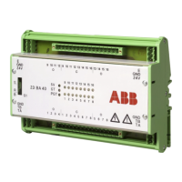
The RTU520 I/O modules are connected to the WRB I/O bus via connector X1. The previous adapter or a communication module is connected at X2 via the WRB I/O bus. The RS485 SPB I/O bus is available on connector X3. In parallel, the fiber optical output can be used (see notice below).
The RS485 SPB I/O bus connector X3 has the following pin assignments:
The usage of the adapter 520ADD02 within an RTU520 DIN rail configuration is shown in Figure 11. The usage of the adapter 520ADD02 within an RTU540 DIN rail configuration is shown in Figure 12 and Figure 13.
The 520ADD02 is designed to prevent damage on the connected modules. It de-energizes the system before plugging or unplugging the I/O bus connectors.
The jumper S1 is used to change the start address of the first I/O Module connected to the 520ADD02. In position 2–3 an offset is calculated to the start address. So it is possible to add up to 8 I/O modules to the previous I/O assembly. In the RTU500 configuration, the parameter "4/4/4/4 addressing mode" has to be selected.
The 520ADD02 is designed for DIN rail mounting. To mount the module:
To remove the module:
The 520ADD02 can be used in various configurations with RTU520 and RTU540 systems.
To prevent unintended disconnection of the I/O bus connectors, end stops (e.g., SAM3, 1SNA190001R0000) shall be used at both ends of the I/O assembly.
Do not change the physical SPB I/O bus medium (electrical, fiber optical) more than once within one RTU I/O bus configuration. Otherwise, communication failures due to signal delay effects can occur.