Description Section 3 Parameter Interface
32 3BSE042835-600
Type Description Keyword
The description field can hold a keyword before the actual description. This
keyword holds information about its usage for the application engineer. All
parameters in Control Module types, Diagram types, and IN_OUT parameters
should have at least one of the first four comments in Table 4.
For Function Block Types parameters only the comments related to EDIT and
NONSIL are applicable.
For control modules, it is very important that the IN and OUT markings of
parameters are correct. The application programmer needs this information to avoid
program loops and to know which parameters to write to and read from,
respectively.
The parameters are shown as IN, OUT, or INOUT ports in Function Designer
dependent of the first characters in the parameter description:
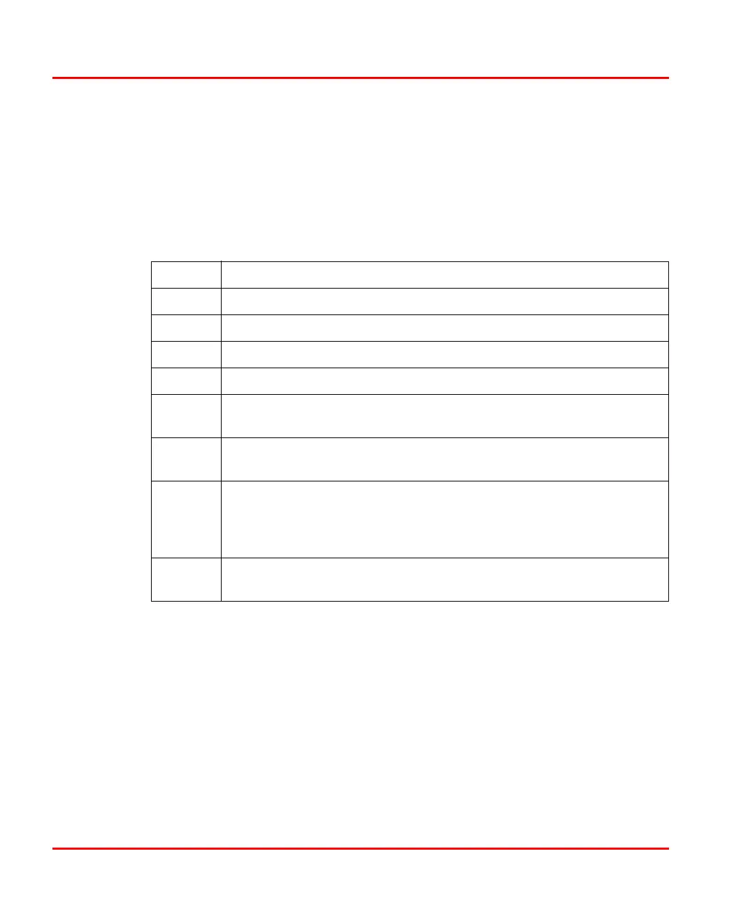
Table 4. Type Description Keywords
Keyword Description
IN The parameter is only read.
OUT The parameter is only written.
IN(OUT) The parameter is both read and written, but mostly read.
OUT(IN) The parameter is both read and written, but mostly written.
NODE Used when the parameter has a graphical connection node (control
modules only).
EDIT The value of the parameter is used the first execution after transition
from Edit to Run mode without initialization. Cannot be changed online.
NONSIL The output parameter marked with NONSIL originates from a restricted
marked sub-object and is not allowed to be used in the critical loop. If
the object is set to SIL1-2 or SIL3, but the parameters are Non-SIL,
then it is possible to obtain partial functionality in the SIL environment.
DEFAULT The output parameters on SIL marked object where the information
originates from restricted sub objects.

 Loading...


