Section 3 Modules Interfaces
M&I – AC 900F Controller 27
The following instructions must be thoroughly read and observed to ensure safe
operation.
• Make sure that the maximum supply voltage (see Section 9, Technical Data)
for modules, sensors and other devices is not exceeded. A module supply
voltage of more than 30 V DC may lead to irreversible damage and destruction
of the system.
• Incorrect wiring (e.g. +/- of the power supply is connected to both L+/L+ or
M/M) will cause a short circuit. This may trip the fuse of the power supply unit
or damage the switch-mode power supply unit.
For general information on safety and precautionary measures, please refer to
the Safety Instructions for the AC 700F/AC 900F.
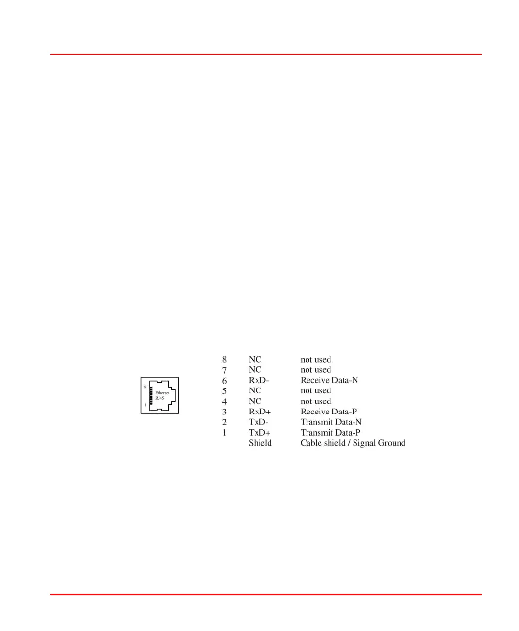
Ethernet interfaces
The on-board Ethernet network interfaces of 100 Mbit/s can be used for
communication between the controllers, gateways, control station and engineering
stations as well as for Ethernet-based field devices to support Modbus TCP or
telecontrol protocol as per IEC-104.
ETH
Ethernet interface_Pin assignment_us.png
For more detailed information on the wiring of the Ethernet interface, please refer to
Section 6, Wiring.
Serial interfaces
A removable 9-pin terminal block is used for the connection to both SER1 and
SER2 serial interfaces of the CPU module. The SER1 and SER2 interfaces can be