10 E-Clipse Bypass Configurations for ACH550 Drives
Installation
Wiring Overview (Supplement to ACH550-UH User’s Manual)
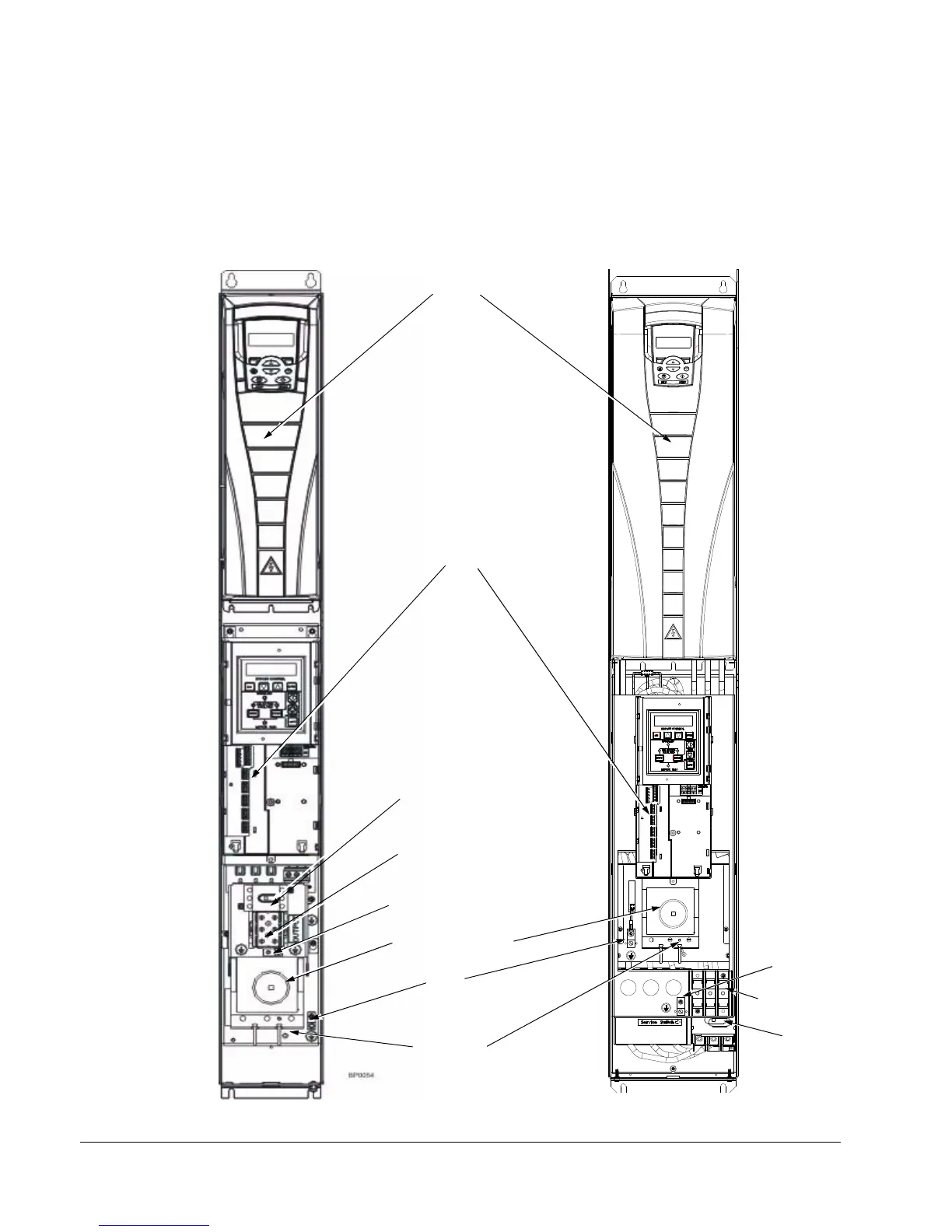
Connection Diagrams – Vertical E-Clipse Bypass
ACH550 Vertical E-Clipse Bypass units are configured for wiring access from the
bottom only. The following figure shows the Vertical E-Clipse Bypass wiring
connection points. Refer to the ACH550-UH User's Manual for control connections
to the drive.
BP0054
ACH550
E-Clipse Bypass
Control Board
Terminals (X2)
Disconnect Switch
or Circuit Breaker
Output
Input Power
Output Ground
Lug(s)
Cable
Terminals
Output
Ground Lug(s)
Output
Terminals
V1/V2 V3/V4
Service Switch
(Optional)
Input
Ground Lug
Terminals
Service Switch
(Optional)

 Loading...


