Chapter 3 – Installation Instructions
ACS 501 Installation & Start-up Manual 3-11
threshold due to regeneration.
To determine if the internal dynamic braking chopper has been supplied,
first check the part number as described in Chapter 2. If the internal
dynamic braking chopper is supplied, an external resistor load bank is
connected to the DC bus terminals.
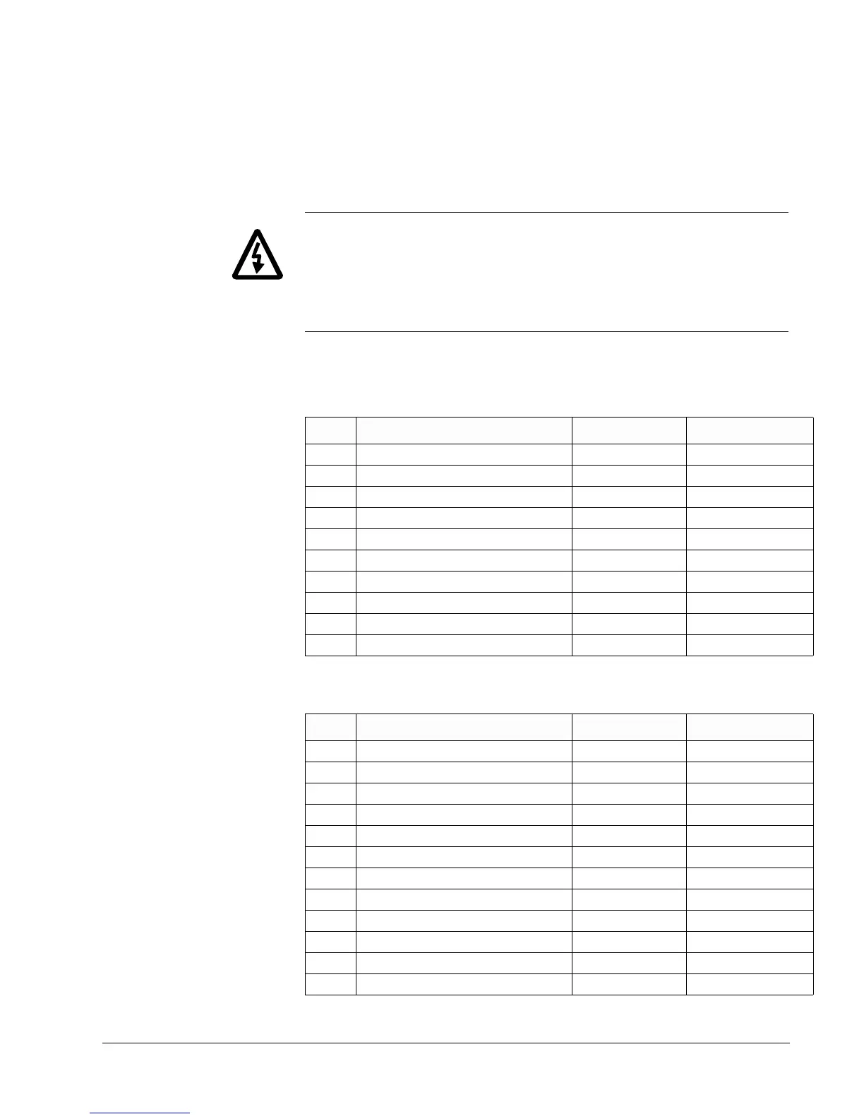
WARNING! Before connecting a resistor load bank to the DC bus terminals,
measure the voltage at the terminals with power applied to the ACS 501. Use
a meter rated greater than 1000 VDC. The voltage should be zero volts. If the
voltage is 1.35 x V
IN
, the internal braking chopper is not present, DO NOT
CONNECT LOAD BANK RESISTORS.
Before connecting the brake resistor, make sure that the resistor value is equal
to or greater than the value indicated in Table 3-9 or Table 3-10.
Table 3-9 Resistor Values For 230 V
Table 3-10 Resistor Values For 480 V
hp Minimum Brake Resistor Value (Ω) Peak Power (w) AveragePower (w)
125.8 44462223
216.0 71713586
312.1 94654733
5 8.9 12907 6454
7.5 6.7 17210 8605
10 5.2 22229 11115
15 3.4 33702 16851
20 2.8 41590 20795
25 2.8 46609 23305
30 2.8 60234 30117
hp Minimum Brake Resistor Value (Ω) Peak Power (w) Average Power (w)
251.5 88924446
3 42.6 10756 5378
5 31.95 14341 7171
7.5 24.2 18931 9465
10 17.7 25814 12907
15 13.35 34419 17210
20 10.3 44458 22229
25 8.4 54497 27249
30 6.8 67404 33702
40 5.5 83180 41590
50 4.9 93219 46610
60 3.8 120468 60234