Chapter 3 – Installation Instructions
3-12 ACS 501 Installation & Start-up Manual
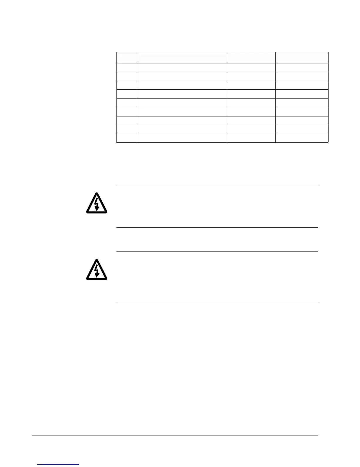
Table 3-11 Resistor Values For 600V
2. External Dynamic Braking Device. If the internal dynamic brake
chopper was not supplied and dynamic braking is required for the
application, an external dynamic braking chopper and resistor load bank
can be connected to the DC bus terminals.
WARNING! The brake control terminals carry a dangerous DC voltage
(1.35 x V
IN
). No device other than an ABB Drives dynamic braking device
may be connected to the positive and negative terminals of Terminal Block
X2.
Insulation Checks
WARNING! Do an insulation check of the motor wiring and the motor before
connecting the ACS 501 to line power. Before proceeding with the insulation
resistance measurements, check that the ACS 501 is disconnected from
incoming line power. Failure to disconnect line power could result in death or
serious injury.
1. Check that the motor wires are disconnected from the ACS 501 output on
Terminals U
2
, V
2
and W
2
.
2. Check that the motor wires are disconnected from the motor and remove
bridging connections at the motor.
3. Measure the insulation resistances of the motor. The voltage range of the
insulation resistance meter must be at least equal to the line voltage, but
not exceeding 1000 V. The insulation resistance must be greater than 1
megohm.
4. Measure the insulation resistance of the motor wiring between the phases
and between each phase and ground. The insulation resistance must be
greater than 1 megohm.
hp Minimum Brake Resistor Value (Ω) Peak Power (w) AveragePower (w)
5 30 20557 10288
7.5 30 20557 10288
10 15 37412 18706
15 15 37412 18706
20 15 48324 24162
25 8.5 59236 29618
30 8.5 73266 36633
40 6 96648 48324
50 6 96648 48324