Chapter 3 – Installation Instructions
ACS 501 Installation & Start-up Manual 3-13
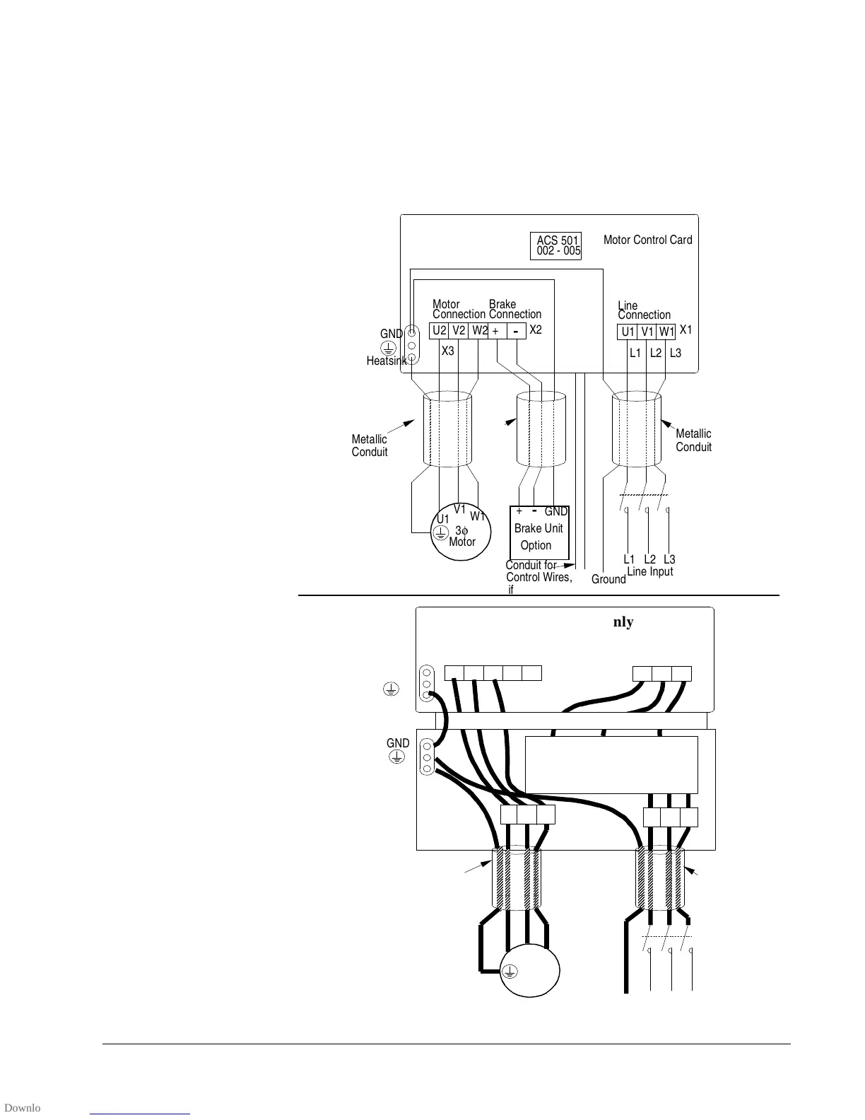
Terminal Connections
To connect the power, motor, and control wires remove the front cover of the
unit by removing the four screws at the corners.
The line input, brake, and motor power output wiring connections are shown
in Figure 3-6.
Figure 3-6 Wiring Connections
AA
AA
AA
AA
AA
AA
AA
AA
AA
AA
AA
AA
AA
AA
AA
AA
AA
AA
AA
AA
AA
AA
AA
AA
AA
AA
AA
AA
AA
AA
AA
AA
AA
AA
AA
AA
AA
AA
AA
AA
AA
AA
AA
AA
AA
AA
AA
AA
AA
AA
AA
AA
ACS 501
002 - 005
Motor Control Card
Line
Connection
U1 V1 W1
L1 L2 L3
U2 V2 W2 +
-
U1
V1
Motor
3φ
Brake Unit
Option
Brake
Connection
Motor
Connection
X3
X2
GND
Heatsink
X1
L1 L2 L3
Ground
Line Input
W1
+
-
GND
Metallic
Conduit
Conduit for
Metallic
Conduit
Control Wires,
if used
Metallic
Conduit
A
A
A
A
A
A
A
A
A
A
A
A
A
A
A
A
A
A
A
A
A
A
A
A
A
A
A
A
A
A
A
A
A
A
A
A
A
A
A
A
A
A
Line
Connection
U1 V1 W1
L1 L2 L3
U2 V2 W2 +
-
U1
V1
Motor
3φ
Motor
Connection
X2
GND
Heatsink
L1 L2 L3
Ground
Line Input
W1
Metallic
Conduit
Metallic
Conduit
AC CHOKE
600 volt units only
GND