Chapter 3 – Installation Instructions
ACS 501 Installation & Start-up Manual 3-5
Table 3-3 Dimensions of ACS 501 Units
Installation Site Power
The ACS 501 is designed for use on a three-phase system. Four wires (three
phase plus a ground wire) are required for the input wiring. Input and output
conductors, and branch circuit protection must be sized to local codes.
At least three (3) separate conduits are required; one each for input power,
output power, and control wiring.
Conduit Size
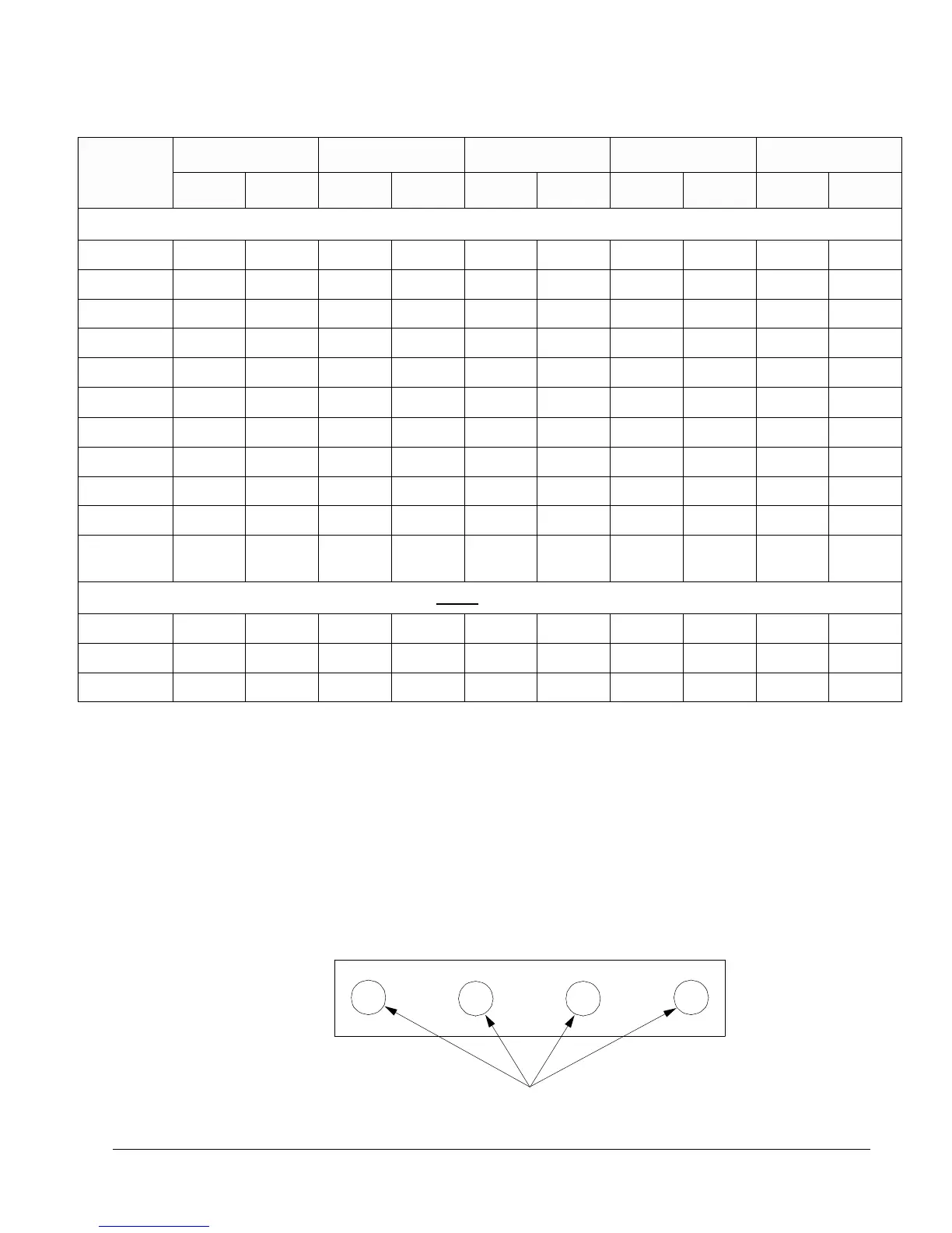
Figure 3-3 shows a bottom view of R2 and R3 ACS 501 drives, and conduit
sizes to fit wire-entry holes.
Figure 3-3 ACS 501 R2 and R3 Conduit Sizes
Dimensions
R2 R3 R4 R5 R5.5
inches mm inches mm inches mm inches mm inches mm
208 to 600 VAC
W 7-7/8 200 9-55/64 250 11-13/16 300 13-13/16 351 13-13/16 351
W1 5-29/32 150 6-57/64 175 8-55/64 225 10-27/32 275 10-27/32 275
H 14-17/64 362 16-3/4 425 19-31/32 507 23-3/4 603 23-3/4 603
H1 13-25/32 350 15-3/4 400 18-29/32 480 22-41/64 575 22-41/64 575
H2 12-9/32 312 14-31/32 380 18-7/64 460 21-45/64 551 21-45/64 551
D 7-25/64 188 8-3/16 208 9-13/16 249 10-5/16 262 12-1/16 307
a 15/64 7 5/16 9 5/16 9 5/16 9 5/16 9
b 35/64 14 45/64 18 45/64 18 45/64 18 45/64 18
c 15/64 7 5/16 9 5/16 9 5/16 9 5/16 9
Unit Weight 17 lbs 8 kg 31 lbs 14 kg 54 lbs 25 kg 74 lbs 34 kg 88 lbs 40 kg
Shipping
Weight
20 lbs 9 kg 34 lbs 15 kg 60 lbs 27 kg 80 lbs 36 kg 96 lbs 44 kg
525 to 600 VAC - Note that the following dimensions do not apply to the 208 to 500 VAC units.
Ht 26.9 683 31.2 794 37.0 940 37.0 940
Ht1 25-61/64 659 30-3/16 767 35-61/64 913 35-61/64 913
Ht2 8.4 214 8.8 224 11.0 279 11.0 279
1/2 in. (12.7 mm)