Chapter 6 – Service and Maintenance
6-10 ACS 501 Installation & Start-up Manual
3. Remove all control wiring from the Control Interface Card.
Note: Terminal Block X50 disconnects from the Control Interface Card in
three whole sections. To do this, lift the interlocking tabs along the top
edge of the three X50 sections and carefully pry the sections straight
outward from the Control Interface Card. Mark the sections to
correspond with their order of assembly on the Control Interface Card.
4. Remove the screws fastening the left side of the Control Interface Card
to the ACS 501 chassis, disconnect the cable from X4 on the Motor
Control Card, and swing the Control Interface Card open to access the
Motor Control Card.
5. Remove all wires from the DC bus capacitors.
6. Set your multimeter to measure resistance.
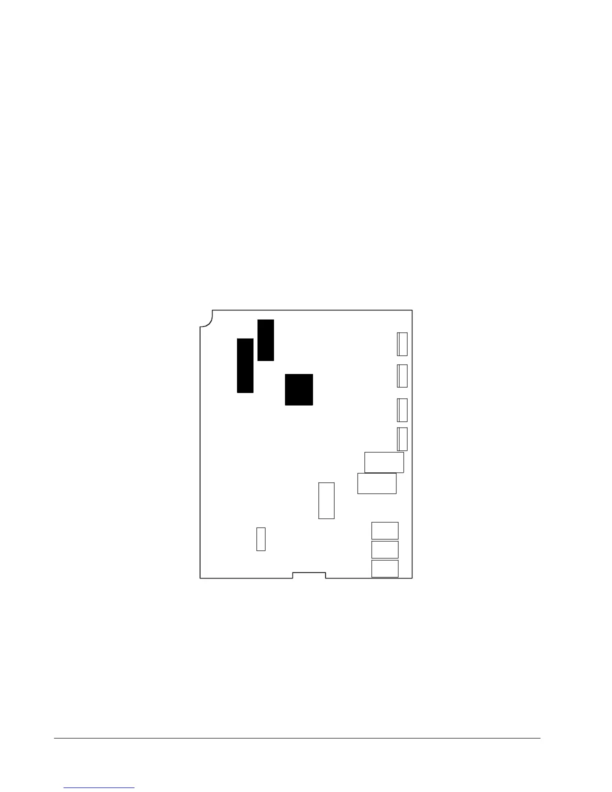
Figure 6-5 illustrates the ACS 501-007 to 040 Motor Control Card.
Figure 6-5 Motor Control Card
7. Connect the multimeter positive test probe to the DC bus capacitor
positive terminal, and the negative test probe to the capacitor negative
terminal.
8. The meter should register a small resistance and rise toward infinite
resistance.
9. Repeat Steps 7 and 8 for each DC bus capacitor. If the reading remains
below 100,000 ohms, replace the capacitor.
X8
X7
X6