Chapter 6 – Service and Maintenance
ACS 501 Installation & Start-up Manual 6-15
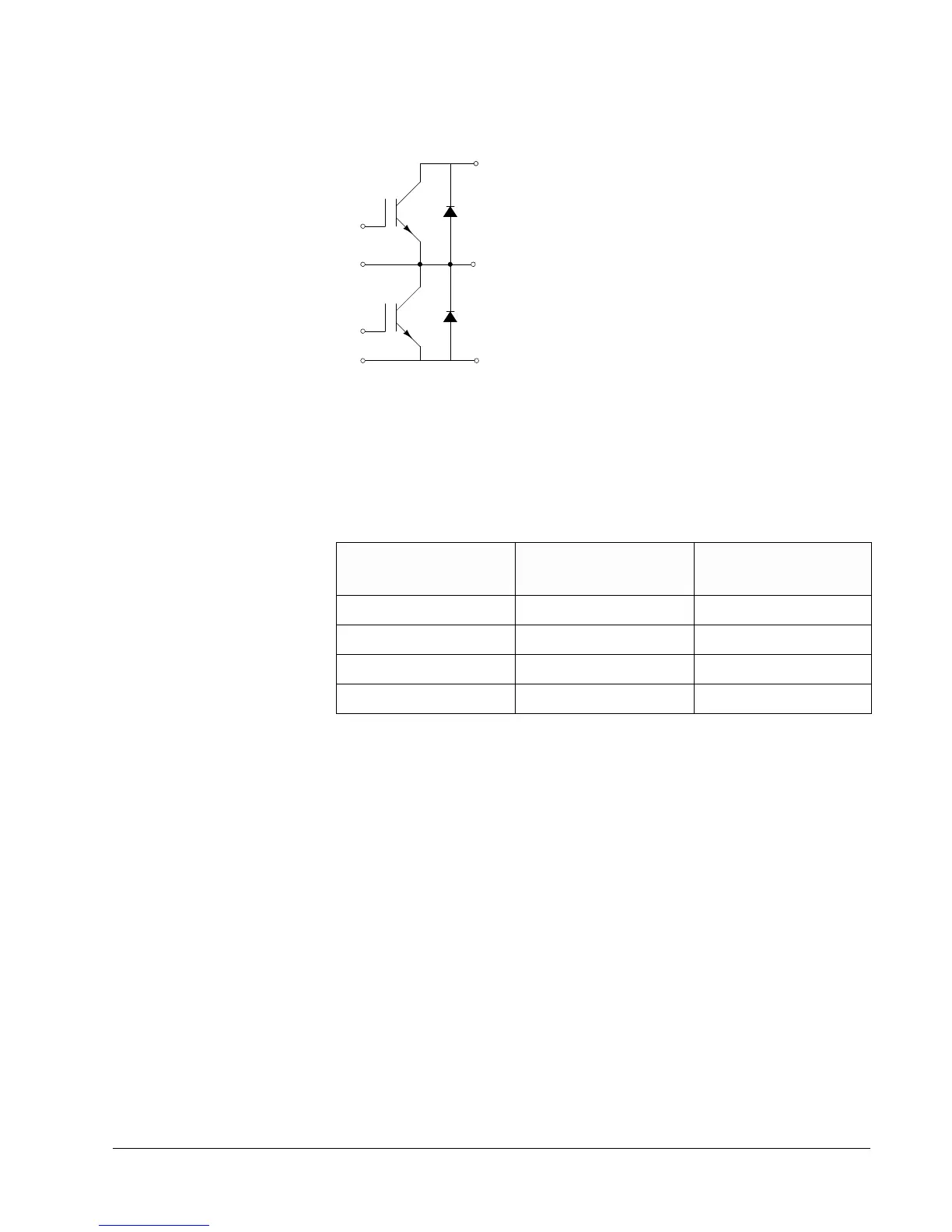
Figure 6-7 IGBT Schematic Diagram and Terminals
8. Set your multimeter to test diodes.
9. Test the IGBTs according to Table 6-5.
Table 6-5 IGBT Test Connections and Readings
10. Repeat the tests in Step 9 for each IGBT. If your readings differ from the
values in Table 6-5, replace the IGBT.
Meter (+) Test Probe to
IGBT Terminal:
Meter (-) Test Probe to
IGBT Terminal:
Reading
C E Over
E C 0.35
B C Over
B E Over
B1
E1
B2
C1
E1
E2
C2
E2