CHAPTER 10 – PREVENTIVE AND CORRECTIVE MAINTENANCE 155
Using the phase module replacement kit
Replacing a phase module
The replacement procedure is basically the same
for DFE and INU phase modules. Steps which are
only applicable for INU phase modules are marked
accordingly.
1. Disconnect all power supplies to the drive and
ground the drive.
For further information, see 10.6.3 De-energiz-
ing the drive locally.
2.
(Only for replacement of INU phase modules of
2 to 4MVA drives)
Install the mounting tray and
the cantilever on the cabinet roof; attach the
lifting hoist and lifting brackets appropriate to
the phase module to be replaced (see 10-14 and
10-15).
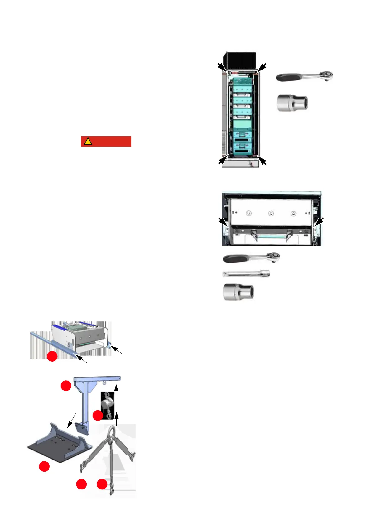
3. Remove the acrylic cover.
4. Remove the screws on both sides of the phase
module.
Hazardous voltages!
When a phase module is removed from the cabinet,
the grounding path between grounding switch and
PE ground busbar is interrupted.
For this reason, connect grounding equipment at
the appropriate locations. The grounding
equipment ensures that hazardous voltages
cannot be fed into the drive from the main power
supply or the motor.
10-15 Using the phase
module replacement kit
10-15
or
• The support tray (4) is installed
onto the cabinet roof, on the
DFE-INU compartment.
• The cantilever (5) is fastened to
the support tray (4).
• The lifting hoist (6) is attached to
the bolt eye of the cantilever.
• The appropriate lifting brackets
(7 or 8) are attached to the lifting
hoist (6).
The module rails (1) are slid under the
phase module.
Similarly for the module trays (2) and (3).
1
5
6
4
7 8