ACS550-02/U2 User’s Manual 13
Installation and commissioning flowchart
Installation and commissioning flowchart
Task See
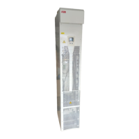
Identify the frame size of your drive, R7 or R8. Technical data: Ratings on page 293 vs.
application requirements
Plan the installation.
Check the ambient conditions, ratings, required
cooling air flow, input power connection, compatibility
of the motor, motor connection, and other technical
data.
Select the cables.
Planning the electrical installation on page 15
Technical data on page 293
For compliance with the EU EMC Directive,
see Technical data: CE marking on page 305.
Option manual (if optional equipment is
included)
Unpack and check the drive.
Check that all necessary optional modules and
equipment are present and correct.
Only intact drive may be started up.
Installation: Moving the drive on page 29 and
Delivery check on page 31
If the drive has been non-operational for more
than one year, the drive DC link capacitors
need to be reformed, see Reforming on page
289.
Check the installation site. Installation: Requirements for the installation
site on page 33
Technical data: Ambient conditions on page
303
Check the insulation of the motor and the motor
cable.
Installation: Checking the insulation of the
installation on page 35
If the drive is about to be connected to an IT
(ungrounded) system or corner grounded TN system,
check that the EMC filter (in frame size R7) and the
varistor (in frame sizes R7 and R8) are disconnected.
Installation: Drive identification on page 31 and
instructions for disconnecting the EMC filter
and varistor, starting from page 44
Route the cables. Routing the cables on page 27
Install the drive. Connect the power cables. Connect
the control and the auxiliary control cables.
Installation on page 29
Check the installation. Installation checklist on page 59
Commission the drive. Start-up, control with I/O and ID Run on page
61

 Loading...