ACS550-02/U2 User’s Manual 301
Technical data
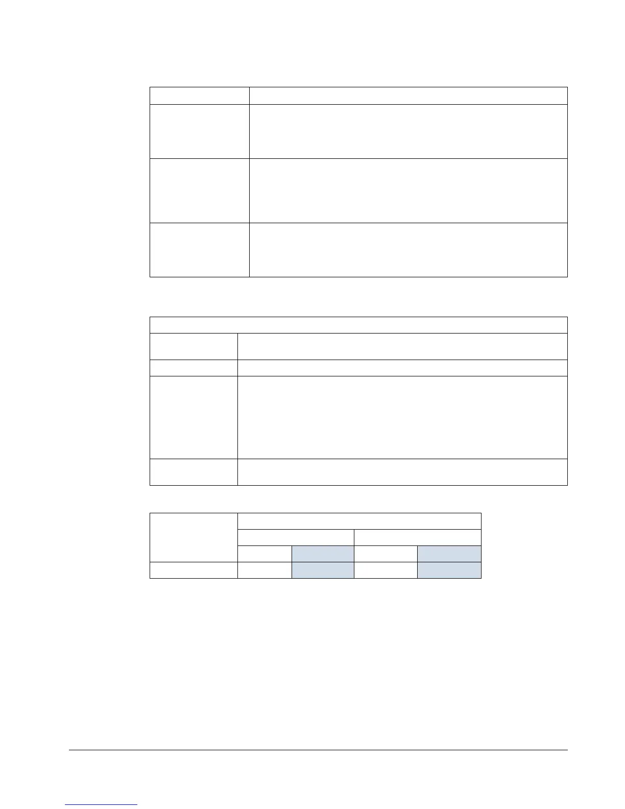
Examples for using the table:
Control connections
Efficiency
Approximately 98% at nominal power level.
Requirements Checking and conclusions
R7 frame size,
Category C2,
100 m (330 ft) cable
Check operational limits for R7 -> for a 100 m (330 ft) cable the basic
unit is sufficient.
Check EMC limits -> EMC requirements for Category C2 are met
with a 100 m (330 ft) cable.
R7 frame size,
Category C3,
150 m (490 ft) cable
Check operational limits for R7 -> for a 150 m (490 ft) cable the basic
unit is sufficient.
Check EMC limits -> EMC requirements for Category C3 cannot be
met with a 150 m (490 ft) cable. The installation configuration is not
possible. An EMC plan is recommended to overcome the situation.
R8 frame size,
EMC limits not
applicable,
300 m (980 ft) cable
Check operational limits for R8 -> for a 300 m (980 ft) cable the basic
unit is sufficient.
EMC limits do not need to be checked as there are no EMC
requirements.
Control connection specifications
Analog inputs and
outputs
See the Hardware description table on page 55.
Digital inputs Digital input impedance 1.5 kΩ. Maximum voltage for digital inputs is 30 V.
Relays
(Digital outputs)
• Max. contact voltage: 30 V DC, 250 V AC
• Max. contact current / power: 6 A, 30 V DC; 1500 VA, 250 V AC
• Max. continuous current: 2 A rms (cos ϕ = 1), 1 A rms (cos ϕ =0.4)
• Minimum load: 500 mW (12 V, 10 mA)
• Contact material: Silver-nickel (AgN)
• Isolation between relay digital outputs, test voltage: 2.5 kV rms, 1 minute
Cable
specifications
See section Power factor compensation capacitors on page 23.
Frame size
Control terminals
Maximum wire size
1
Torque
mm
2
AWG N·m lbf·ft
R7, R8 1.5
16 0.4 0.3
1
Values given for solid wires.
For stranded wires the maximum size is 1 mm
2
.

 Loading...


