Electronic Commercial Water Meter
AquaMaster™ 3 Electrical Installation
26 IM/AM Issue 13
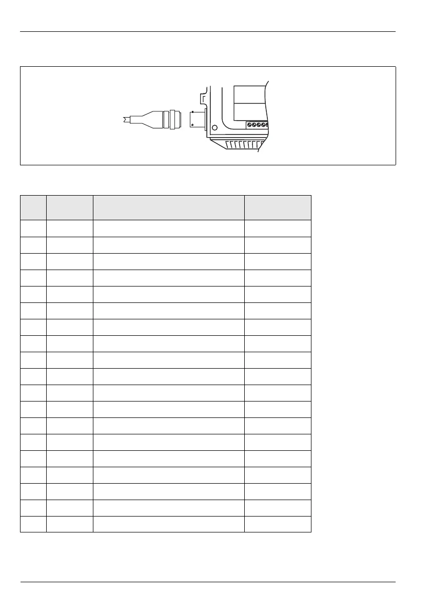
3.3.3 Connector Input/Output Connections
Fig. 3.18 MIL Connector Connections
Pin Signal Function Color
(Output Cable)
A–Reserved
B–Reserved
C–Reserved
D O/P 1 Forward Pulses or Forward & Reverse Pulses Orange
E O/P 3 Alarm Output White/Red
# When Remote
Comms. Option is fitted
F O/P 2 Reverse Pulses or Direction Indicator Blue
G O/P Com† Common Drain Wire/Screen
H – Reserved * Not fitted on older
cables
J I/P Gnd Input Common White
K I/P+ Contact Input Violet † Note Caution
regarding fully floating
outputs.
Recommended
protection for floating
output systems is to
connect G to J.
L RXD Receive data (serial input connection) # Turquoise
M TXD Transmit data (serial output connection) # Brown
N RTS Request to send # Red/Black *
P CTS Clear to send # Yellow/Red *
R–Reserved
S–Reserved
T RI Ring Indicator # Yellow
U–Reserved
V Serial GND Comms Ground # Green
Table 3.1 MIL Connector Connections