Installation and operating instructions, ATS021
1SDH000759R0002, L4106
26
7. Using automatic transfer switch ATS021
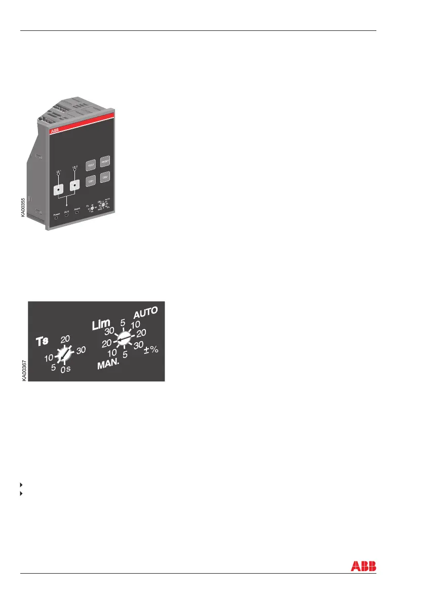
7.1 Interface
Figure 7.1 Interface of ATS021
7.2 Confi guration
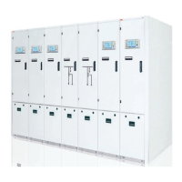
7.2.1 Rotary Switches
Figure 7.2 Selection of delay time and voltage threshold, the factory settings are shown in the fi gure
Ts = Delay time for automatic switching
The delay time is the time before activating the switching sequence and the back-switching sequence.
Available selections for the delay time are: 0, 5, 10, 15, 20, 25, 30 s.
Lim = Voltage threshold
If difference between the rated voltage and measured voltage is greater than threshold value set by
parameter Lim, the line is considered to have an anomaly. The same threshold value applies to difference
between the highest and the lowest phase voltage. Available selections for voltage threshold are:
In MANUAL Mode: ± 5, ± 10, ± 20, ± 30 %
In AUTOMATIC Mode: ± 5, ± 10, ± 20, ± 30 %.
The MAX acceptable voltage threshold selection for 480 Vac voltage is + 20% and the MIN acceptable
voltage threshold selection for 208 Vac is - 20%. By setting the voltage threshold, the unbalance is also
set to the same level. The operating mode and the voltage threshold are selected simultaneously by
setting the Lim rotary switch to the desired position. For example, when the Lim rotary switch is set to
“20 MANUAL”, the device is in the manual mode and the voltage threshold is ±20%.
7. Using automatic transfer switch ATS021