2-4
MN716
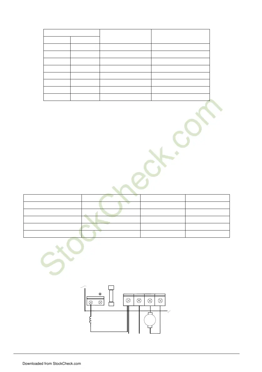
Table 2-2 Armature Fuse Chart (F2 Power Board)
Motor Horsepower Approximate DC Motor
Current Amps
Fuse Rating
(AC Amps)
90VDC 180VDC
1/8 1/4 1.3 2
1/6 1/3 1.7 2-1/2
1/4 1/2 2.5 4
1/3 3/4 3.3 5
1/2 1 5.0 8
3/4 1-1/2 7.5 12
1 2 10.0 15, 20 *
1-1/2 3 15.0 25
The Logic Control board contains a low amperage fuse F1 (.150 amp Littlefuse 3AG, normal blow or
equivalent), which protects the control transformer and other components against catastrophic failure,
Figure 2-1. Under normal circumstances, this fuse should never blow.
If the fuse should blow, refer to Troubleshooting Guide.
Motor Field Connection (Shunt Wound Motors Only)
Full Voltage Field Connection (Shunt Wound Motors Only)
Do not use F+ and F- terminals for any other motor type.
Connect the motor field leads to F1 (+) and F2 (-) terminals of TB2 as shown in Figure 2-2 and Table
2-3.
CAUTION! Do not connect motor armature leads to Terminals F+ and F-. Do not use Terminals F+ and F- for any
purpose other than to power the field of a shunt wound motor. Shunt wound motors may be damaged
if the field remains energized without armature rotation for an extended period of time.
Table 2-3 Field Connections (Shunt Wound Motors Only)
AC Line Voltage (VAC) Armature Voltage (VDC) Field Voltage (VDC) Field Connections
115 90 100 F+ and F-
115 90 50 F+ and L1
230 180 200 F+ and F-
230 180 100 F+ and L1
230 90* 100 F+ and L1
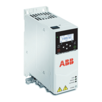
Half Voltage Field Connection (Shunt Wound Motors Only)
Do not use F+ and F- terminals for any other motor type.
Connect the motor field leads to F1 (+) and L1 (-) terminals of TB2, as shown in Figure 2-3 and Table
2-3.
Figure 2-3 Half Voltage Field Connection
A
+
-
ARMATURE
TB1
F+ F-
AC LINE
FUSE
F1
FIELD
TB2
AC LINE
INPUT
L1 L2 M1 M2
Downloaded from StockCheck.com