2-3MN716
Electrical Connections
To avoid erratic operation, do not bundle the AC line and motor wires with signal or control wiring.
Do not bundle motor wires from multiple controls in the same conduit. Use shielded cables on all
signal wiring over 12 (30 cm). The shield should be earth grounded on the control side only. Wire the
control in accordance with the National Electrical Code requirements and other local codes that may
apply.
AC LINE
Verify the AC line voltage matches the line voltage of the control. Connections are shown in Figure 2-2.
The BC200/BC201 has a single AC line fuse connected in series with terminal L1. Fuse (F1) is
25A for BC201 and 20A for BC200). Be sure to fuse each conductor which is not at ground potential
(do not fuse neutral or grounded conductors).
A separate AC line switch or contactor must be connected as a disconnect switch so that contacts
open each ungrounded conductor. See Table 2-1.
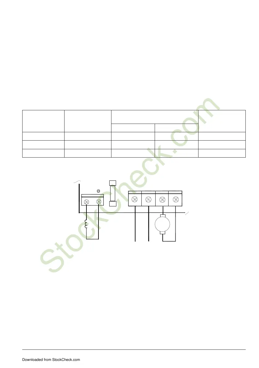
Table 2-1 Terminal Block Wiring Information
Terminal Block
Designation
Connection
Designation
Supply Wire Gauge
(AWG - Copper)
Maximum Tightening
Torque
(lbs- in)
Minimum Maximum
TB1 (Power Board) F+, F- 22 14 3.5
TB2 (Power Board) L1, L2, M1, M2, GND 18 10 3.5
TB1 (Logic Board) Logic Connections 22 14 3.5
Figure 2-2 Power Connections
-
+
A
FIELD
F1
AC LINE
FUSE
TB1
ARMATURE
F+ F-
L1 L2 M1 M2
TB2
AC LINE
INPUT
Ground Connection
Connect all ground wires (earth) to the green ground screw that is provided on the inside of the
control to the right side of TB1 (not shown), tighten to correct torque, Table 2-1.
Motor Armature Connection
Connect the motor armature positive lead (+) to Terminal M1 and negative lead (-) to Terminal M2, as
shown in Figure 2-2.
An armature fuse (F2) is also provided with a rating equal to the maximum RMS rating of the control.
It is recommended that the correct size armature fuse be installed, depending on the rating of the
motor and form factor (RMS/AVG current). Fuse type should be Littlefuse 326 ceramic or Buss ABC, or
equivalent. A fuse chart is presented in Table 2-2, which suggests appropriate armature fuse ratings.
However, the specific application may require larger fuse ratings based on ambient temperature, CL
set point and duty cycle of operation.
Downloaded from StockCheck.com