2-6
MN716
Enable
Warning: When the Enable jumper is installed, the drive and motor will start and run when AC power is applied,
when power is restored after a momentary power loss, or after an overload or TCL fault is reset. The
user must ensure that automatic start up of the driven equipment will not cause injury to operating
personnel or damage to the driven equipment. The user is responsible for providing suitable audible or
visual alarms or other devices to indicate that the drive may start at any moment. Failure to observe
this warning could result in severe bodily injury or loss of life.
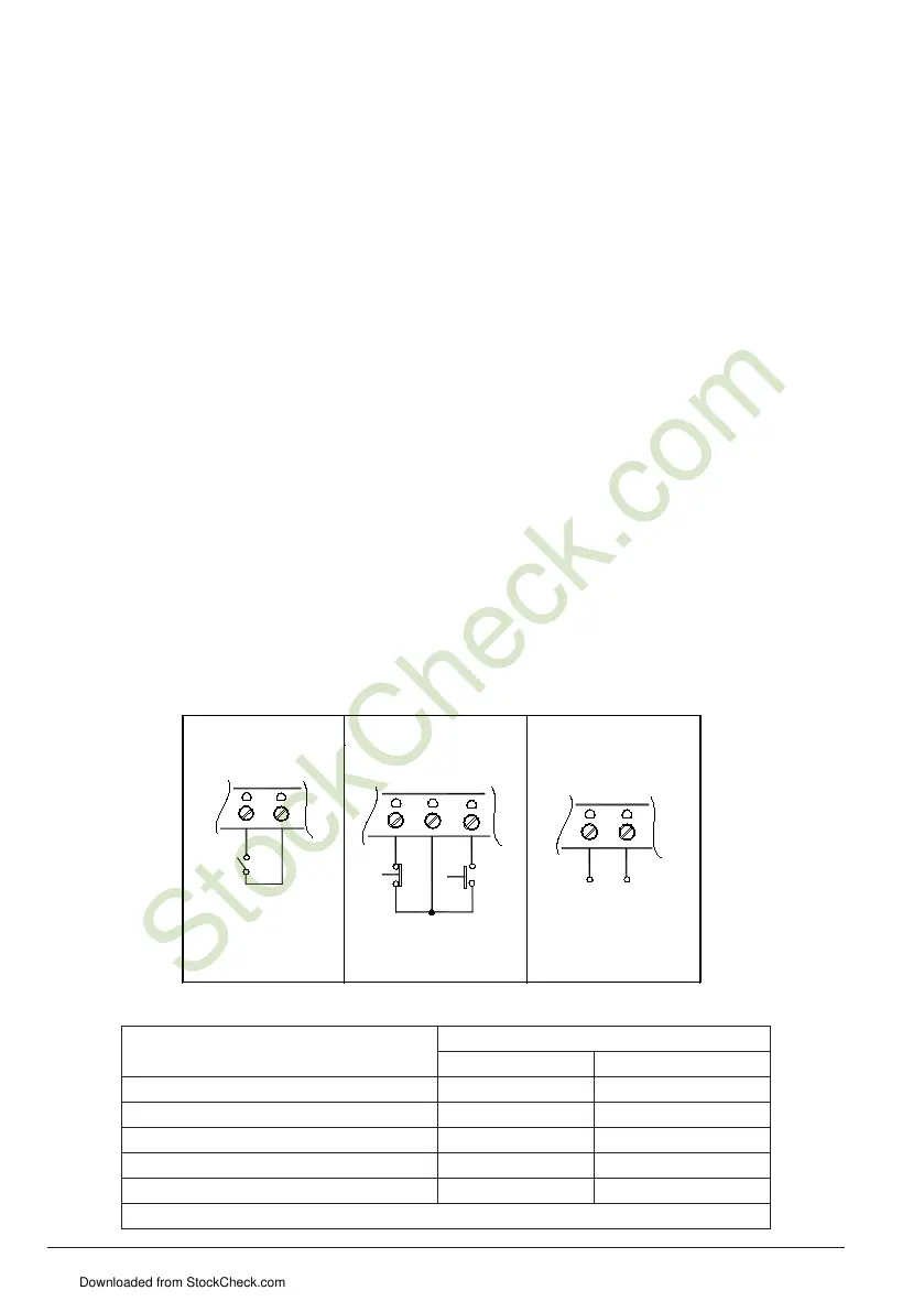
Control may be started and stopped with the Enable circuit. To use this feature, install a jumper across
TB1, terminals 5 and 7, (Start/Stop circuit), and connect Enable contacts to TB1, terminals 8 and 9.
When the contacts close the control is in the Enable state and the motor will start and run. When the
Enable contacts open, the control is in the Inhibit state and the motor will coast to rest. See Figure
2-6A.
Note: If Enable is not used, install a jumper between terminals 8 and 9 or control will not operate.
Start/Stop Circuit
A standard 3-wire start/stop push button control station may be connected to TB1 terminals 5, 6, and
7, allowing remote start/stop control. If AC input power is cycled On/Off, or if the timed current limit
mode has timed out, the start push button must be used to restart the motor. See Figure 2-6B.
Note: The Start/Stop function may be bypassed by connecting a jumper wire across the Start and Com
terminals of TB1.
Note: The Timed CL function will operate only when the Start/Stop mode is used.
Note: The Control will not start if the input AC line voltage is below 20% of nominal, (190 VAC on 230 VAC
input).
OUTPUT RELAY
S.P.S.T. relay contacts (terminals 3 and 4) are used to signal a warning or to shut other equipment
down if control goes to an Inhibit state. Rating of contacts are 1A-28VDC, 0.5A-115VAC. See Table 4-4
for relay control state vs. contact state. See Figure 4-6C.
Figure 2-6 Enable, Start/Stop and Relay Circuit Wiring
Start/Stop Circuits
FIGURE C –
CLOSE TO RUN
OPEN TO COAST STOP
8 9
TB1
COAST
TO STOP
(NORMALLY
CLOSED)
5 6 7
START
(NORMALLY
OPEN)
TB1
3 4
TB1
RELAY CONTACTS
Figure 4-6A
-
Enable
Figure 4-6C
Relay Contacts
-
Table 2-4 Control State vs. Relay Contact State
Description of Control State
Relay Contact State
Using Start / Stop Start / Stop Bypassed
Power Off O O
Power Applied O X
Control in Stop Mode O N/A
Control is started with Start button X N/A
Control has Timed Out in TCL O N/A
O = Open, X = Closed, NA = Not Applicable
Downloaded from StockCheck.com