9
4 ELECTRICAL INSTALLATION…
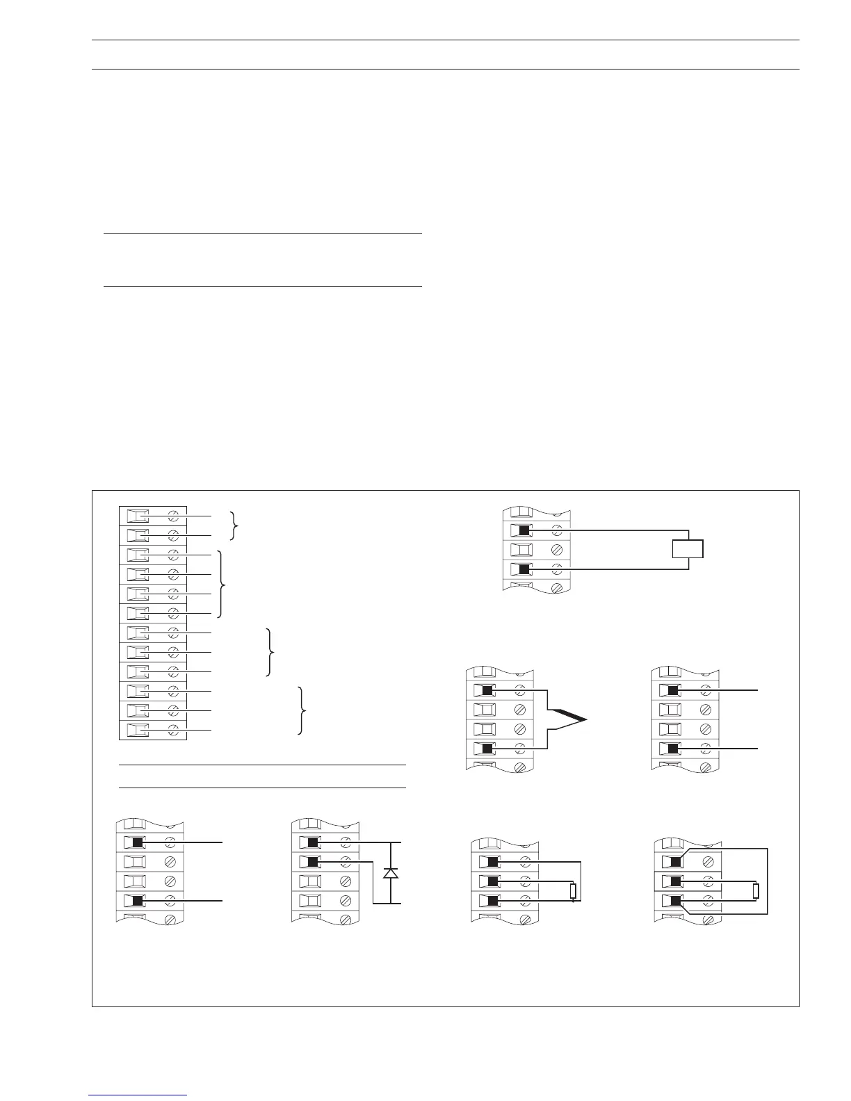
4.2.2 Voltage and Current – Fig. 4.5
Input impedances:
Low voltage (mV) >10MΩ
Voltage >10MΩ
Current (mA) 100Ω
4.2.3 2-wire Transmitter Input – Fig. 4.5
Power for the transmitter is supplied by terminal 6.
Note. The voltage across terminals 4 and 6 is 20V
(nominal). This is due to internal voltage drops across a
shunt resistor and measurement circuitry.
4.2.4 Thermocouple – Fig. 4.5
Use correct compensating cable between the thermocouple
and the terminals – see Table 4.1 (previous page).
Automatic cold junction (ACJC) is incorporated but an
independent cold (reference) junction may be used.
Note. Not applicable on Type 2 Modules.
A – Summary of Connections
1
2
7
8
9
10
1
12
Analog Output (See
Note
below)
+
–
Relay Output
Normally Open
Common
Normally Closed
Logic Inputs (See
Note
below)
Common
Logic 1
Logic 2
Analog Input – see B to H
3
4
5
6
D – 2-wire Transmitter
(not available on non-upgradeable version)
4
6
+
–
–
+
Tx
See
Note
below
B – Voltage
3
6
–
+
C – Current
(non 2-wire transmitters)
3
4
–
+
G – 3-wire RTD
4
5
6
Red
White
Red
E – Thermocouple
3
6
–
+
H – 2-wire RTD & Resistance
5
6
White
Red
Link
4
F – Low Voltage (mV)
3
6
–
+
4.2.5 Resistance Thermometer (RTD) – Fig. 4.5
If long leads are necessary it is preferable to use a 3-lead
resistance thermometer.
If 2-lead resistance thermometers are used each input must be
calibrated to take account of the lead resistance.
4.2.6 Logic Inputs – Fig. 4.5
The two logic inputs accept either volt-free (switch) or TTL (5V)
input types and can be used for remote switching of many
recorder functions, e.g. chart stop/go, alarm acknowledgment,
totalizer reset etc. Refer to the
Programming Guide,
IM/C1900–PGR or IM/C1900–PGC.
4.2.7 Analog Output – Fig. 4.5
4.2.8 Relay Output – Fig. 4.5
Relay specification:
Type single pole changeover
Voltage 250V AC 250V DC
Current 5A AC 5A DC
Loading (non inductive) 1250VA 50W
Isolation, contacts to earth 2kV RMS
Fig. 4.5 Channel Connections
 Loading...