5
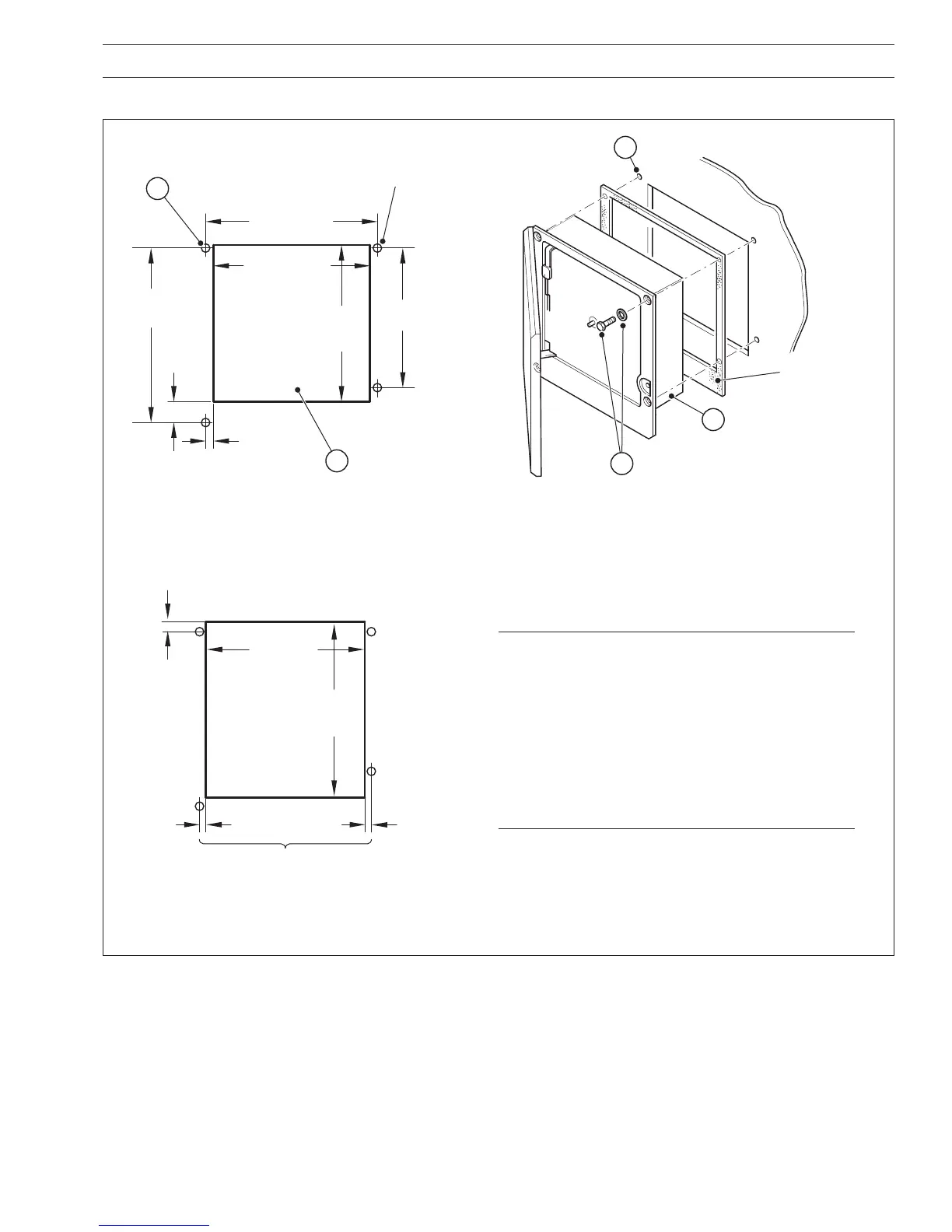
3.2.2 Panel Mounting – Fig. 3.5
3 MECHANICAL INSTALLATION
Locate instrument
in cut-out
Secure in panel using
four bolts, washers and nuts
Drill four suitable holes
Optional gasket
(see
Note 2 below)
4
5
3
Dimensions in inches (mm)
Cut hole in panel
(see
Note 1 below)
Mark four mounting holes
12.72 (323.08)
minimum
11.25
(285.8)
14.00 (355.6)
14.19
(360.4)
0.64 (16.25)
1.70
(43.2)
4 holes 0.281 dia.
or tap for
1
/4 in. thread
2
12.72
(323.1)
minimum
1
13.7 (348.0)
maximum
0.15 (3.8)
minimum
0.20
(5.0)
0.15 (3.8)
minimum
14.6
(371.0)
maximum
Ensure cut-out positioned centrally
between mounting holes
Minimum Cut-out Dimensions
Maximum Cut-out Dimensions
Notes.
1. The instrument can be inserted into a panel cut-out
of any size between the minimum and maximum
dimensions illustrated, provided the cut-out is
positioned centrally relative to the fixing holes. If the
panel cut-out is larger than the maximum, a locally
manufactured adaptor plate will be required.
2. If panel-mounting to NEMA 4X hosedown standard
is required, a continuous bead of suitable silicon
sealant must be applied beween the case flange
and the panel. Do not use the optional gasket.
Fig. 3.5 Panel Mounting
 Loading...