10
2
5
4
4
5
6
L
N
(L)
Link
(see
Note 2
below)
100%
0%
100%
0%
Motorized
Valve Drive
Valve
Positioner
Power
Supply
Four Relay Module
3
6
10
10
11
11
Type 1 and/or Type 2
Modules (see
Note 1
below)
Type 1 or Type 2
Module
1st
Module
2nd
Module
1st or 2nd
Module
(N)
4
5
6
Link
(see
Note 2
below)
100%
0%
Motorized
Valve Drive
Type 1 or Type 2
Module
1st or 2nd
Module
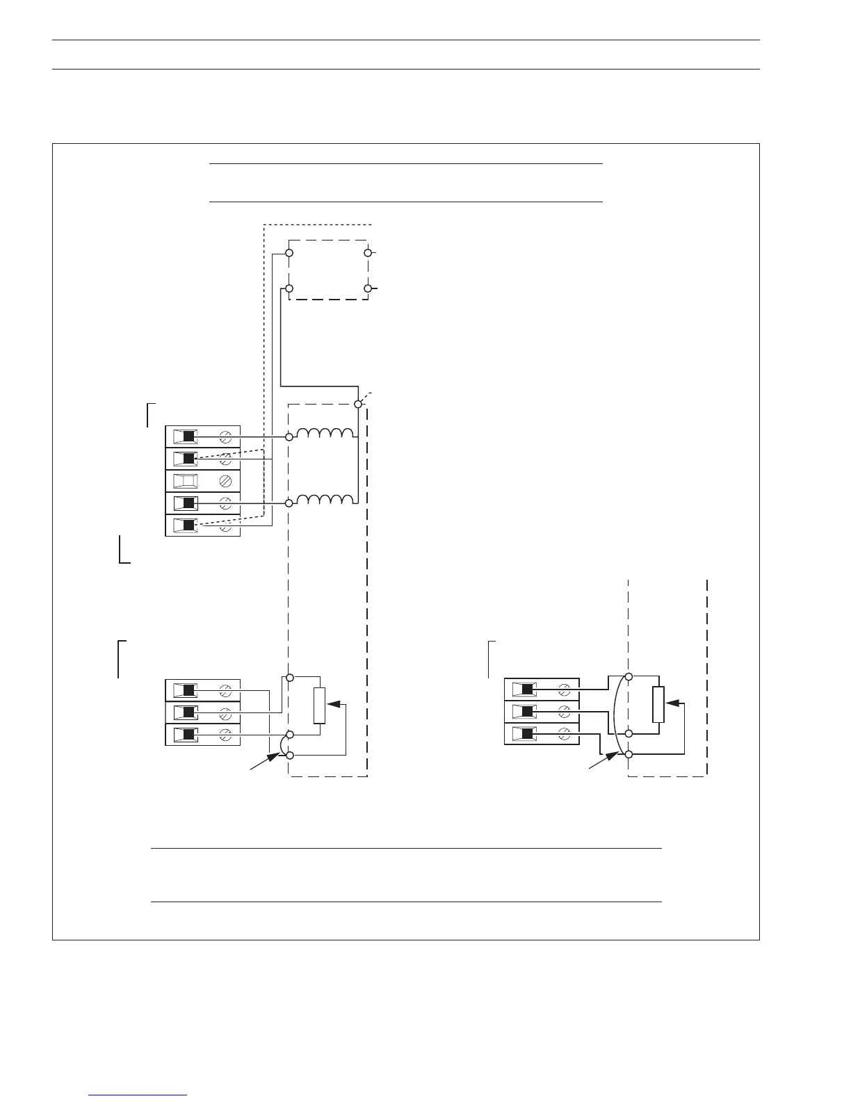
A – Standard Feedback Slidewire Configuration B – Alternative Feedback Slidewire Configuration
…4 ELECTRICAL INSTALLATION
4.2.9 Motorized Valve – Fig. 4.6
A motorized valve with or without feedback requires 2 relays (common and normally open terminals) to drive the valve in either
direction. Any two relays can be allocated for this function. Fig. 4.6 A shows two possible combinations.
Notes.
1 Type 1 and type 2 modules have one relay output, therefore two modules are required.
2 Link must be connected at valve drive end, not at the controller terminals.
Fig 4.6 Motorized Valve Connections (using feedback slidewire)
Note. For valves with position feedback using low voltage (mV),
voltage (V) or current (C), refer to Fig. 4.5 B, C and F for connections.
 Loading...