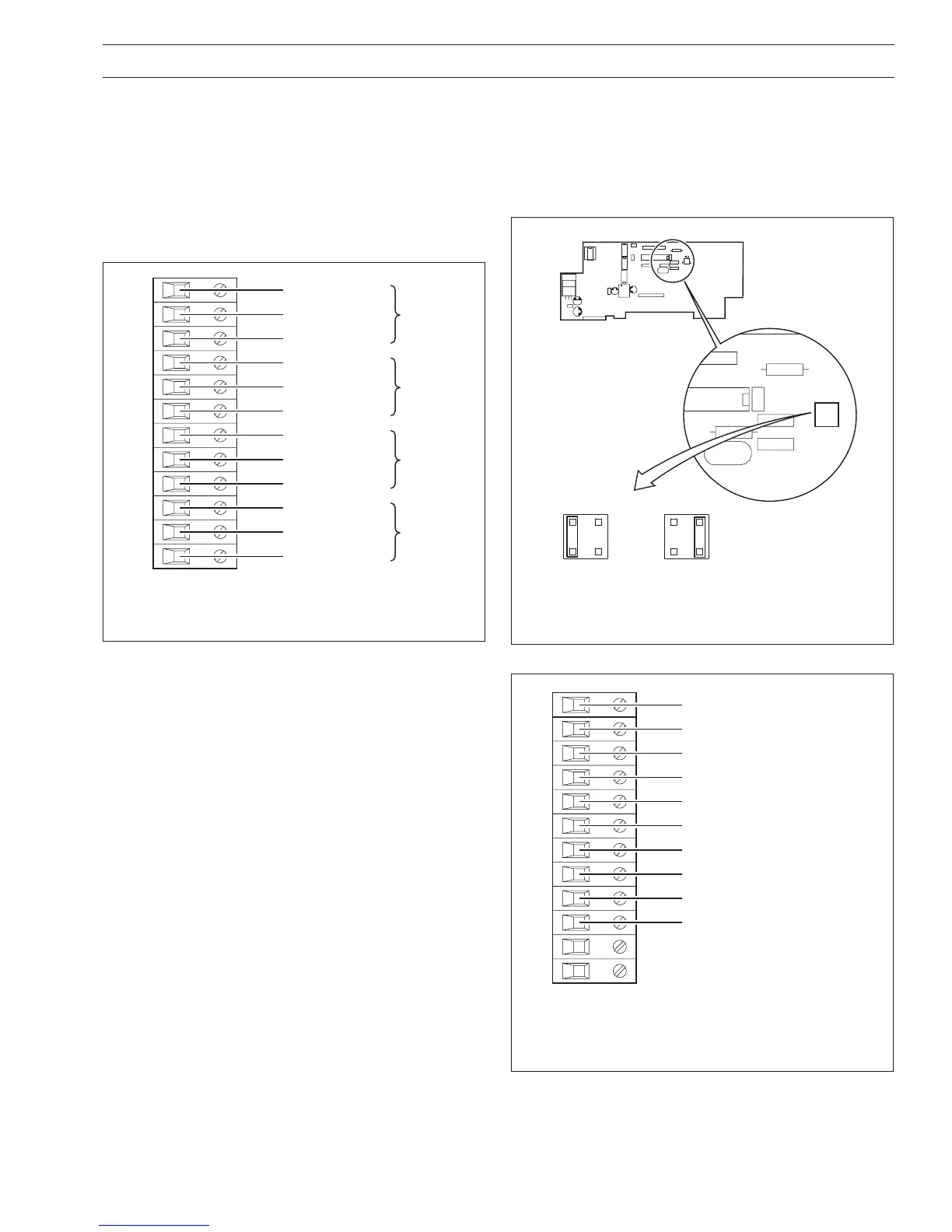
4.3.3 Eight Digital Inputs or Outputs
(Module Types 4 and 5 respectively) –
Figs. 4.8 and 4.9
A plug-in link is used to select the board's function; digital inputs
or digital outputs – see Fig. 4.8. The maximum current drain from
each TTL output must not exceed 5mA.
Fig. 4.8 Selecting the Digital Module Function
(Module Types 4 and 5)
Fig. 4.9 Eight Digital Inputs or Outputs Connections
(Module Types 4 and 5)
4 ELECTRICAL INSTALLATION…
1
2
7
8
9
10
11
12
3
4
5
6
Normally Closed
Normally Open
Relay 1
Common
Normally Closed
Normally Open
Relay 2
Common
Normally Closed
Normally Open
Relay 3
Common
Normally Closed
Normally Open
Relay 4
Common
4.3 Module Connections
4.3.1 Standard I/O or Analog + Relay
(Module Types 1, 2 and 7) – Fig. 4.5
The connections are the same as Channel connections to the
main board. Refer to Section 4.2.
4.3.2 Four Relay Module (Module Type 3) – Fig. 4.7
Fig. 4.7 Four Relay Module Connections
(Module Type 3)
 Loading...