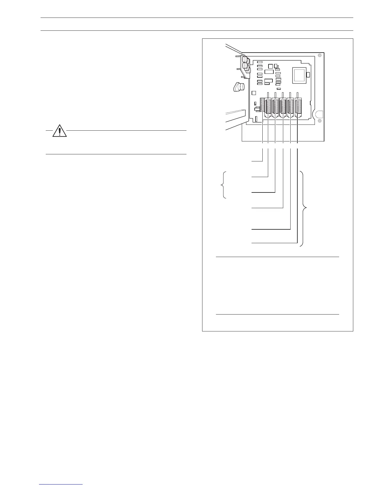
4.1 Identifying the Input/Output Modules – Fig. 4.2
To gain access to the modules, open the door and chassis – see
Fig. 2.2. There are six module positions as shown in
Fig. 4.2.
4.2 Channel Connections
Channel 1 connections are made directly to the terminal block
mounted on the motherboard.
Other Channel connections are made to standard I/O modules,
fitted in positions 2, 3 or 4 – see Fig. 4.2.
Warning. The maximum channel to channel
voltage (between any 2 channels) must not exceed
500V DC.
Notes.
• Module positions can also be used for
additional I/O modules (module types 1 and
2) for use with math functions.
• The module type is marked on the
component side of the PCB Refer to Table
2.1 for the module types and module
position options.
Fig. 4.2 Module Positions and Functions
4 ELECTRICAL INSTALLATION…
 Loading...