Timing relays
159
1SVC 440 795 M0100
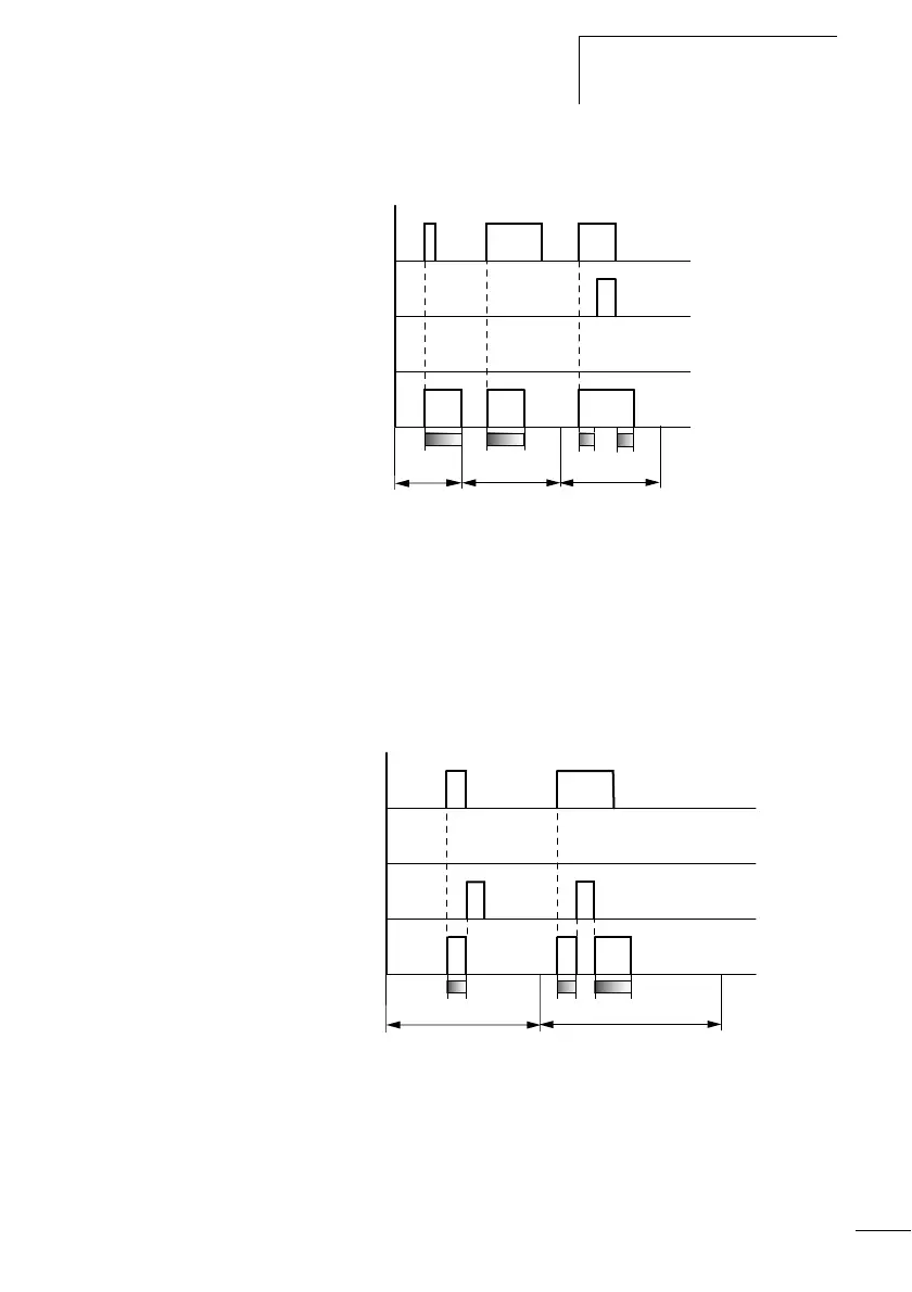
Timing relay, single pulse
Figure 69: Signal diagram of timing relay, single pulse 1
1: Trigger coil TTx
2: Stop coil HTx
3: Reset coil RTx
4: Switching contact (n/o contact) Tx
• Range A: The trigger signal is short and is lengthened
• Range B: The trigger signal is longer than the set time.
• Range C: The stop coil interrupts the timing out of the set time.
Figure 70: Signal diagram timing relay, pulse shaping 2
• Range D: The reset coil resets the timing relay.
• Range E: The reset coil resets the timing relay. The trigger coil is
still activated after the reset coil has been deactivated and the
time is still running.
A B
t
1
+ t
2
= t
s
t
s
t
s
C
1
2
4
3
t
D
E
t t
s
1
2
4
3
 Loading...


